Technical & Maintenance | Upgrades & Style | Used A8 Buyer's Checklist |
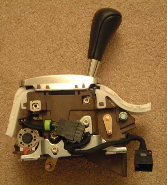
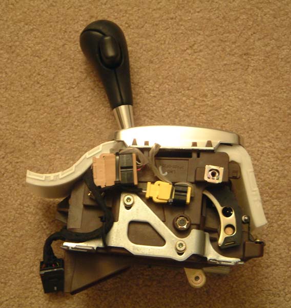
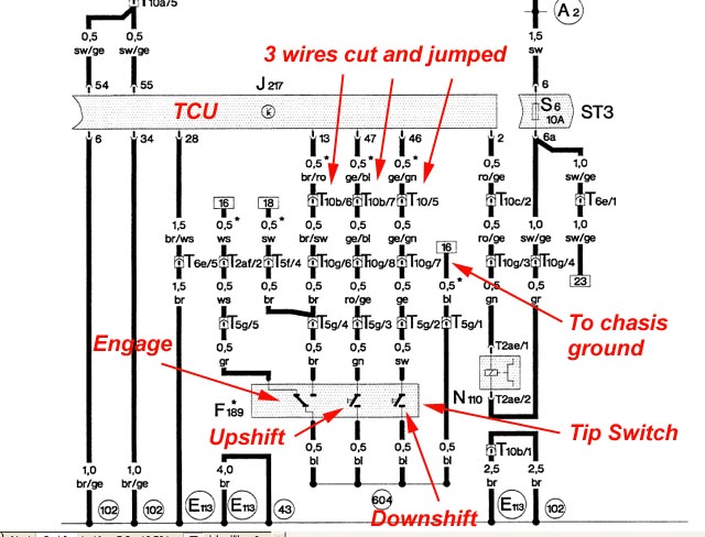
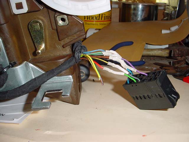
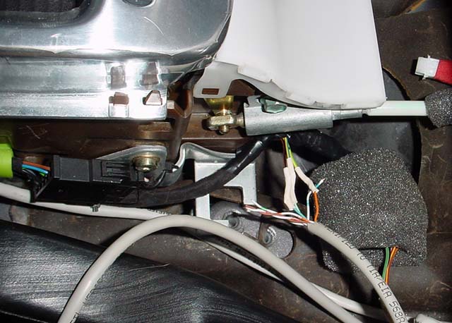
| Tiptronic Wire Connections for 1997 to 1998 Electrical Connectors | ||
| Wire Function | 1998 Shifter Wires | 1997 Wire Connector Wires |
| Shift Lock Solenoid | Black/Yellow | Gray |
| Shift Lock Solenoid | Red/Yellow | Green |
| Tip Backlight | Grey/Blue | Black |
| Ground | Double Brown | Double Blue |
| Tip Selector Light | Double Grey/Green | Purple |
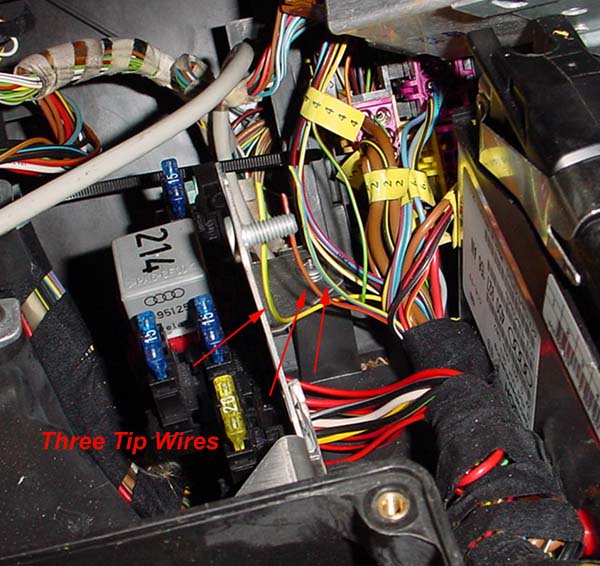
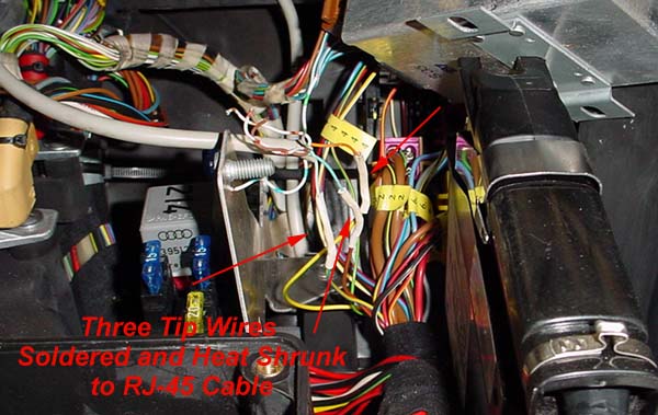
| Tip Shift | Yellow/Blue | Green (RJ-45 Cable) |
| Tip Engage | Brown/Black | Blue (RJ-45 Cable) |
| Tip Shift | Yellow/Green | Orange (RJ-45 Cable) |
Technical & Maintenance | Upgrades & Style | Used A8 Buyer's Checklist |