Integrating an iPod into the Audi A8
By Paul Waterloo
General
Installation of an iPod (which is actually a MP3 player) into an Audi A8 is pretty easy. What is a MP3 player? It's a device that plays songs in MP3 format. iPod's come with large hard drives, from 10 to 30 GB. You can store your entire music collection on it! A 20 GB unit can store over 4,000 songs (about 400 CD's) in MP3 format at CD quality.
My iPod sounds about as good as my CD player, especially with songs that are recorded in high quality. Why take six CD's with you when you can take your whole collection?
You can also create playlists, which you define, it plays what you program into the iPod. So you don't have to listen song to song, album to album.
The iPod MP3 player. This procedure works for any MP3 player.
Integrating the iPod into the A8 Stereo System
All A8's which have a six disc CD player in the trunk (1997 to 2001) is applicable to this procedure. Actually, any car that has line level CD inputs into the head unit can use this procedure.
The iPod also has line level outputs through the stereo mini jack where the headphones plug in. These line level inputs can be switched into the head unit and the iPod can be played on the stock stereo system.
The switching is accomplished by the installation of a relay and a switch which energizes/deenergizes the relay to switch inputs into the head unit. The wires that feed the input to the head unit must be cut and the relay installed with the CD player and iPod as inputs.
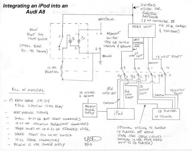
To switch between sources, a switch on the dash is pressed while the radio is selected to "CD". Here is the basic schematic for the installation. The relay switches between the CD player and iPod.
Schematic for integrating the iPod into the A8. Click on the image for a full size PDF version.
Procedure
The first step is to assemble the relay. The relay needs to have the wiring attached to it. This is accomplished by cutting the wires to attach to it and soldering them to the relay terminals. It would be easiest to use colored wires to differentiate between right, left and common. If using the Radio Shack relay, polarity doesn't matter, the relay will pick up when hooked up either way.
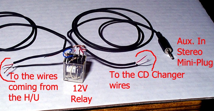
The first picture is from Jeff Bipes' web page, which was the basis for this procedure. Please note that second picture on that page showing "to power amp" is for the output to the Bose speakers, and have nothing to do with this procedure. You will be hooking up your inputs to the lower left side of the picture, labeled "CD".
Jeff Bipes' relay set up.
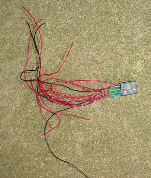
Paul Waterloo's relay set up with Radio Shack 275-214 relay.
To attach the wires to the relay, strip the wire end, tin the wire and tin the relay terminal. Put the wire up against the relay terminal and using a soldering iron, melt the solder (that was already tinned on the wire and terminal), remove the iron and hold still until it hardens. Do not create a "cold solder" by moving it as it cools. This is visible by a dull solder joint versus a shiny solder joint.
Place a piece of heat shrink tubing down around all the soldered connection and shrink in place.
The relay now has to be connected to the head unit. Remove the radio with a pair of the DIN tools (you will need 4 if you have an 2000 or newer). They're available from Pro.Fit International, and other suppliers. You will also want to get the hooked dentist tool to remove the center air vents to get access to the switches in the dash. Instructions for use are with the tools; it's pretty straight forward. When ordering them, get a couple of those dash tools as well, you'll need them some day. Great for removing wood trim pieces to clean around the edges and polishing.
Once the radio is removed, find the CD input wires into the head unit. This is marked on the back of the radio. Here are the needed wires for the Delta, Concert and Symphony radio. These wires are also marked via a sticker on the head unit.
Delta and Concert Radios
The Delta and Concert radios have the same pin assignments. On connector I (20 pin connector), use:
18 - Common input into head unit
19 - Left channel input into head unit
20 - Right channel input into head unit
For the switched power to the on/off switch, use the 12 VDC electric antenna output on the radio. This can be found on connector III (black 8 pin connector), terminal 5.
Both Delta and Concert radios have the same pin assignments.
Symphony Radio
The Symphony radio has a slightly different connector, but has the same pin assignments as the Delta and Concert. On connector I (20 pin connector), use:
18 - Common input into head unit
19 - Left channel input into head unit
20 - Right channel input into head unit
For the switched power to the on/off switch, use the 12 VDC electric antenna output on the radio. This can be found on connector III (black 8 pin connector), terminal 5.
Symphony radio connector.
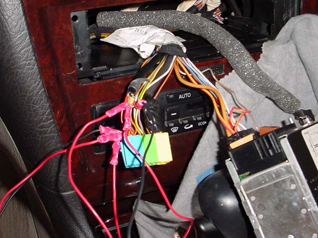
Cutting these wires can be tricky, there is only about 1" of wire to deal with. Cut it half way between the radio plug in connector and where the sleeve starts around the wiring that goes back to the CD player. These are very small gage wires, about 22 or 24. Using a butt crimp connector, crimp connections onto these wires. I had to cut the insulation back on the butt connector to the actual metal connector inside to make it fit easier.
Once all six wires have been cut back, crimp relay wires into proper connections per the wiring diagram. Once this is complete, energize the stereo and ensure the CD player still works. If one channel doesn't work, you have a problem with either the left or right channel, if both do not work, you have a problem with the common leg.
Splicing the relay into the CD input wires.
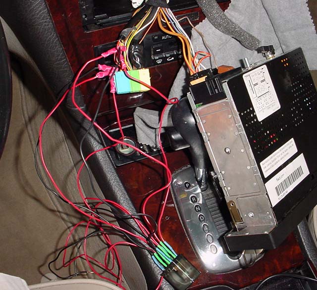
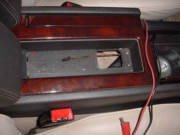
Now you will have to attach the 6' stereo mini plug wire to the other three leads to the iPod input. Depending on where you will mount the iPod, you'll most likely need to remove the right hand side center console panel. You can find complete instruction on how to remove and reinstall the panel here. Once the right hand panel is clear, you will need to snake the wire from under the armrest (that's where I put mine) to the dash area.
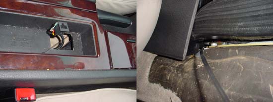
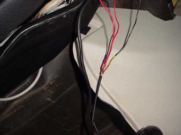
This is accomplished by pulling the carpet up under the center armrest by just prying it up with a screwdriver. You'll find a metal plate under the carpet, pull it up too. You'll have to unscrew the two screws holding the RJ-45 phone connector in place. Here's what you'll see:
Remove carpet and metal plate, there will be a large hole there. Use an electrical snake from the right of the console near the shifter (with side panel removed) and run to the opening.
Route the electrical snake from right side of center console to hole in center console.
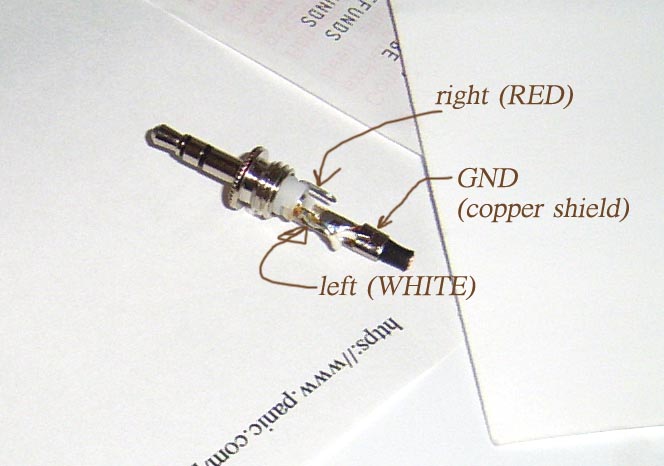
After the wire is snaked, run the wire from the relay to the stereo mini jack wire. Solder and heat shrink. Most mini jack wires will have the white wire being left, red wire as right, and the other being common. The picture below shows a mini jack connector. The common can also be shielded.
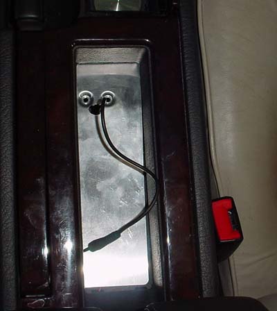
iPod wires connected to relay input wires.
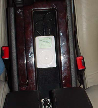
iPod installed without charger attached with carpet replaced.
Installing the Switch to Toggle Inputs
A new switch must be installed to toggle the inputs between the CD player and iPod inputs. You could use any maintaining two position switch, I used a front foglight switch and mounted it in the dash.
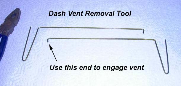
To remove the switch and gain access to the wiring, it is easiest to remove the center vents. These are removed by using the hooked dentist tools from Pro.Fit International. They can also be fabricated using instructions below. Snake them in the center vent, and engage them in the hole just behind the left and right vent control (D shown below). Use a flashlight and you'll see where they engage. It is best to have a friend help you the first time, the vent is a friction fit and in tight! Pull as hard as you can and it should slowly come out. Once it is out, disconnect the two wire connections and you'll have easy access to the switches.
Removing the center vents. To fabricate tool,
wire should be 3 mm (0.118") thick and "X" should be 6 mm (0.250").
Use a Coat Hanger to Make the Dash Vent Removal Tool
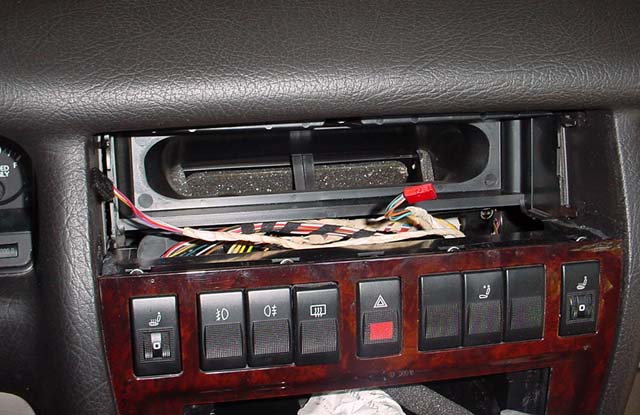
Center Vent Removed
Remove the blank switch by pushing it out from behind. Using the new switch, attach the wires to terminals 1, 2, 5 and 6. This is accomplished by making up jumpers and using insulation displacement connectors and connecting to an adjacent switch terminal 1 and 2. Use spade connectors to connect to the switch. The grey/blue wire provides lighting to the switch (red background lighting) and the brown wire provides a ground path.
Ensure the wiring diagram is followed exactly otherwise the "on" green indication light might not light up. The relay has to be installed to terminal 6 on the switch and then jumpered over to the adjacent switch ground. The Radio Shack relay is not polarity sensitive, you can hook it up either way.
The power supply for the relay is taken off the switched (+) 12 VDC for the electric antenna. This is found on terminal 5 of connector III. Use an insulation displacement connector to tap into the wire. Using the power supply for the electric antenna will ensure that the power supply for the relay will only be used while the radio is on. If the ignition is turned off and a unswitched power supply was used, the relay would stay energized when the car was not on if the dash switch was selected to "iPod". If a switched power supply was used, you could not use the iPod with the ignition off. This problem is solved by using the electric antenna switched power supply.
After the switch is wired up, switch it on and off with the radio on and ensure you hear the relay pick up and drop out. Plug in the iPod and select the stereo to "CD". Toggle between iPod and CD inputs and make sure it works. You can control the line level inputs of the iPod by using the volume while it is playing.
Optional Wiring
With the iPod connected above, it does not have a power supply to it, using only its internal battery to power it. Additionally, the CD player will operate while toggled to "iPod" if the CD cartridge is in the CD player with CD's in it.
WILL POST CHARGER INSTALLATION PROCEDURE LATER.
To turn off the CD player while using the iPod, the fourth pole of the relay (which wasn't used) can be used to switch the power supply from the head unit to the CD player. This is a (+) 12 VDC power supply that switches the CD player on and off when the head unit is selected to "CD". To switch off the CD player when the switch is selected to "iPod", just cut the switched power supply wire to the CD player as described in the line level inputs above. Connect it across terminals 1 and 9 on the Radio Shack relay.
This will allow the (+) 12 VDC from the head unit to the CD player when the CD is selected, and open this circuit when the dash switch is depressed, selecting "iPod". The dash indication and radio will not have a display (this has not been verified).