Background
This procedure outlines the replacement of the front control arms. They are commonly referred to as “control arms” although Audi has specific names for each one (see below). There are a total of eight arms, four on each side comprised of two “uppers” and two “lowers”.
The Audi translation below will help if you are ordering parts from the dealer or need to search in the Bentley manual.
Guide Link = lower curved arm Track Control Link = lower straight arm Upper Rear Link = upper round/straight arm Upper Front Link = upper curved arm
Let's talk strategy. While it is possible to replace arms individually, it doesn't always make sense from a labor standpoint. In theory, some of the arms hold up better than others. Isolating a particular arm for replacement though is tricky. Once you read through the procedure, you'll understand why audipages recommends replacing all eight as a “set” and changing the sway bar links and tie rod ends at the same time. This approach minimizes the amount of labor and will make your front-end feel like new.
Why replace the arms at all? Telltale symptoms are, squeaking, rattling, groaning over bumps, knocking and alignment issues. If you have the original arms and are over 70,000 miles, consider replacement if you are experiencing any of the symptoms above.
It is imperative that you get an alignment done after performing this procedure. The nature of the Quattro system disguises what normally makes a 2 wheel drive car feel out of line. In other words, just because the steering is not pulling to one side doesn't mean the alignment isn't out of spec.
Changing all of the arms, swaybar links and tie rod ends is easily a $2,000 plus job at the dealer. This particular procedure has one of the highest payback in terms of savings. This is a time consuming job but not overly complicated.
Before Performing the Job
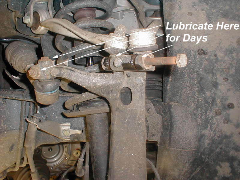
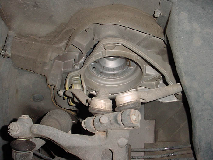
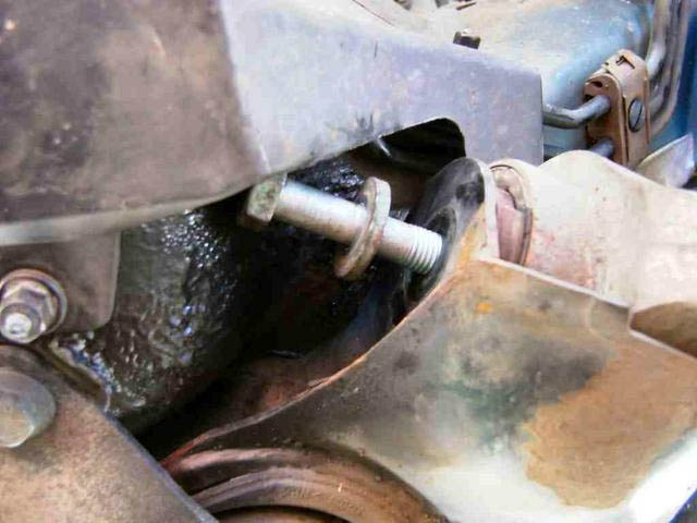
Before beginning this project, it is very important that you spray penetrating oil (PB Blaster) onto the pinch bolt shown below, preferably over several days. If this bolt cannot be removed it has to be drilled out which will add hours to this procedure.
While you are waiting for parts to arrive, keep soaking it everyday. If you plan on changing the tie rod ends, soak those bolts/nuts as well.
Spray the areas shown and tie rod end threads if planning on changing them.
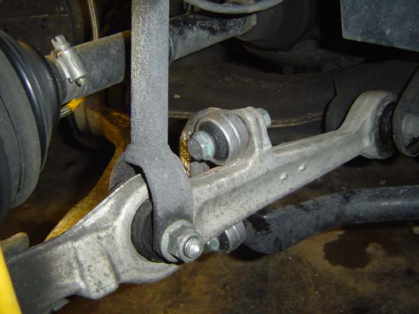
Prior to ripping everything apart, see if the bolt can be partially removed as shown above. If not, you have to determine whether you want to forge ahead with this project. There is no way to remove the upper arms with the bolt in place, so you have to figure out a way to remove it or take it somewhere to have it done.
This is a showstopper if you can't get past this point…..
Time: 7-8 hours if first time and bolt is not frozen
Parts: Control arm “kit” which usually contains 8 arms, sway bar links, tie rod ends, hardware. I have had good luck getting the Meyle kit from blauparts.com which has all of the hardware all the hardware (with exceptions below) for around $500.
Tools and Materials Required
Usual assortment of wrenches and sockets. An impact gun is a huge help as there are lots of nuts and bolts to be removed.
Alignment tool (looks like a tapered center punch)
PB Blaster
Circlip pliers
Pickle fork
Circlip pliers
Anti-seize
Bungee cords
Torque wrench
Optional - Upper pinch bolts (typically not included with kits that contain hardware)
Lower curved arm bolts (these get cut, must have and not included in kits)
Closed end wrench, 16mm on one end, 18mm on the other. Sears has them and you'll use it a lot for this job
Additional 16mm and 18mm wrenches. Make sure you have one of each AND the wrench above. Sockets won't fit in a lot of places
so you'll be using two at a time of the same size.
Procedure
This procedure details replacing all eight control arms, tie rod ends and sway bar links. Refer to the relevant section if you are only doing a partial replacement. I recommend doing one side at a time for two reasons:
It leaves one side intact for reference
Enables you to finish a side and be able to move the car. The operative word being "move", not drive J
1a) Determine status of pinch bolt described at the top of this procedure. If removable, continue. If not, stop here before proceeding.
1b) Jack up one corner of the car. Leave the jack in place and put a jack stand underneath as a backup. The car will be in the position for many hours so makes sure that it's absolutely stable. Remove the wheel.
2) Remove the belly pan and set aside.
3) Remove the (2) 13mm sway bar bolts on each side.
4) Disconnect the sway bar links from the lower, straight control arms on each side (16mm). You should now be able to remove the sway bar and put it aside.
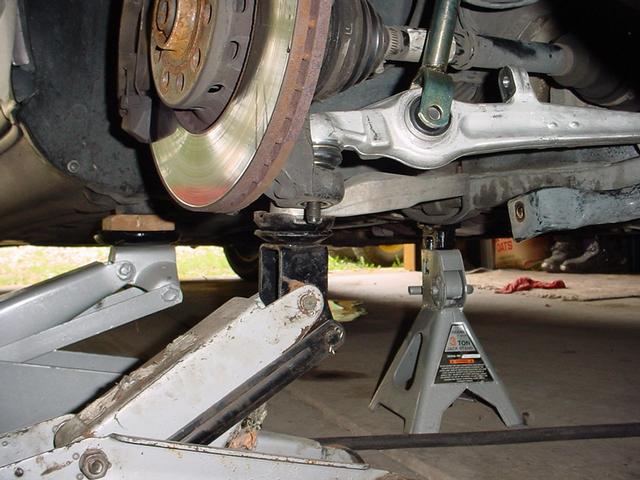
WARNING
Have a jack underneath to support the entire wheel housing. Once you start removing the arms, the only thing supporting all of the weight becomes the axle and tie rod assembly, which you don't want to do !
5) Remove the bolt that connects the bottom of the strut to the straight arm. The strut will stay connected to the car from up above.
6) Remove the nut/bolt that connects the lower straight arm to the frame. Once removed, take a rubber mallet and knock it down so that it
is only connected by the ball joint end.
7) Under the hood, remove the plastic cover so you can access the two rubber plugs the cover the strut nuts. There are (2) 13mm nuts that need to be removed with a deep socket. Put your hand on the strut while removing because that's all that is holding the strut in place.
Optional method: you can leave the strut in place and remove it along with the sub-frame. It makes it a little heavier and obviously a little bigger to maneuver out but there is room. The advantage to doing it this way is that the strut nuts are much easier to access when on the ground.
Once the two nuts are removed, the whole strut assembly can be removed and set aside. While not covered here, this is a perfect time to change your struts if needed.
8) Remove the balljoint end of the lower straight arm by removing the nut on the bottom and use a pickle fork to get it out. Another method is to loosen the nut so that it's even with the top of the threads and use a hammer to drive it out. This gives you a bigger area to hit with the hammer.
BOTH methods are destructive so only use when replacing the arm with a new one.
Status Check: At this point, the swaybar, strut assembly and lower straight-arm should be removed.
Note: I have changed the order of this procedure after doing it a bunch of times. I think it's easier to swap out the upper arms first before
removing the lower curved arm. The only reason is that it helps keep the strut housing supported a little more.
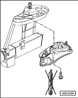
9) The two upper arms are pretty easy because you actually remove the whole “sub - frame” which they connect to.
Also, the hardware is a little more protected and therefore rust is not an issue.
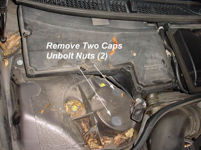
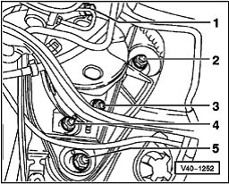
Upper Sub Frame Nut Locations
Under the hood, there are five 18mm nuts that need to be removed (see pic below). They are what hold the sub frame to the body of the car. Remove the two black covers so you can access all of them (you should already have at least one off already to remove the strut bolts). At least one on the passenger side is obstructed by a hose, so hunt around a little.
You can see the relative positions in the picture below and the Bentley diagram above. The Bentley pic is almost looking straight down at the strut tower.
Remove all five nuts.
Remove upper pinch bolt and disconnect upper arms from housing. Have bungee cords handy because the whole wheel bearing housing will want to flop around. The upper arms are what keep it in place.
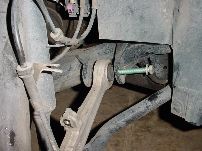
Remove the nut & bolt inside the wheel well that hold the add'l brace shown in the pic below.
At this point, the whole sub frame will drop down and out (a little wiggling required). Move it onto the floor or bench to swap the arms.
Upper Sub Frame Removed
Depending on the year, you might have an add'l brace shown above - it is not “required” to be reinstalled according to the Bentley. If you do not reinstall, put the bolt and 18mm nut in the hole where the brace was located as shown above.
10) The straight arm has a circlip, which needs to be removed first. The circlip is put in at the factory to help during production. It is not required for reinstallation but I put it back on anyway. Reinsert the special bolt for the straight arm and the clip will hold it in place until you get the sub frame reinstalled.
NOTE: Both arms have a metal spacer with a taper on one side where the bolts go through the sub frame. They might fall out when the sub frame and/or arm is removed. No big deal - the taper faces downward. Just make sure that they are there when you reassemble. If one or more of the spacers are “missing” look up into the hole and it might be stuck inside.
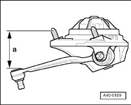
11) The upper curved arm removal and reassembly is pretty straightforward. The only thing you need to be aware of is the position of the arm in the sub frame before tightening the nut. This is important because if the arm is in the wrong position it will stress the bushing prematurely. Once it's in position, torque to 37 lbs + Ľ turn BEFORE you install the sub frame (you won't have access to the nut otherwise).
Dimension “a” should equal 97mm (+/- 2mm) or 3.81”
At this point, the straight arm will be fairly loose in the sub frame only being held by the circlip and the curved arm will be locked in position. Time to reinstall the sub frame.
STOP: Make sure the tapered spacers have been reinstalled and that the curved arm has been torqued to spec.
12) Reinstall sub frame. Torque 5 nuts to 74 lbs.
13) Connect the upper arms to the wheel bearing housing by reinserting the pinch bolt. Use anti-seize in case you need to do this again. Tighten to 37 lbs.
14) Reinstall strut assembly, torque 13m nuts to 15 lbs. Pop rubber grommets over holes and reinstall plastic covers. You're done under the hood for this side.
15) Reinstall lower straight-arm on the ball joint end first and hand tighten the nut. Lift up the arm into position so that you can reattach to the frame and also to the strut.
This will take a little trial and error to get everything lined up so the bolts go through. The tapered alignment tool is a big help here.
I would re-use the factory nut with the large washer. If your kit came with a lock nut, it's too small and will torque down on the insert inside the wheel bearing
which can slide out - Hand tighten for now.
Did you lose the orientation of the bolts? That's why you do one side at a time!
Ok, now that the uppers arms are swapped out and the lower straight arm is removed and installed, it's time to tackle the lower curved arm.
16) The curved arm is a little tricky because the nut is inaccessible without loosening the sub frame and prying it down to allow clearance for removal.
Someone came up with the idea of reversing the new bolt, which eliminates this step.
In order to do that, you have to cut the old bolt off. There are many ways to do this - body saw, grinder, dremel tool, and sawzall. The bolt is extremely hard and will take a little time to get all the way through. Trust me, even if it takes you 15 minutes a side, cutting the old bolt is a much better option all around.
I bought an expensive air body saw for this job and it just doesn't have enough torque for this kind of cutting. A cutoff wheel on a grinder is the quickest but access is a little harder. Although bulky, a sawzall with a good metal blade works well. Cut roughly 1/3, rotate, and repeat until you're all the way through.
Tip: You can gain more access by loosening the fender liner and peeling it back out of the way. Remove three 10mm plastic bolts (one on the bottom and
two inside the wheel well) and remove and the Philips screw on the side. Pull the liner off of the three metal studs and use a bungee cord to hold it out
of the way.
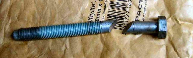
Due to sub frame interference, the curved control arm bolt won't come out and it is easiest to cut with a die grinder and cut off wheel.
Lower curved control arm bolt cut for removal.
17) At this point, you can reinstall the new lower arm. Installation is the opposite of removal with the exception of inserting the new bolt in the opposite direction. Where you saw the nut previously would now be the bolt head. Working the bolt through the hole in the frame is a little tricky but you'll get it.
Install the ball joint end the opposite of removal. I would re-use the factory nut with the large washer - same issue as the straight arm.
· Tighten both ends basically hand tight. All final torque settings will be done on the ground.
18) Reinstall sway bar links to the lower straight arm. Don't connect the sway bar end just yet until you complete the other side. Torque to 52 lbs.
Everything should be back together now. It cannot be stressed enough that you have to put the car back on the ground, bounce it up and down a few times and begin torquing all of the loose nuts/bolts. It's tedious but necessary to do it this way so you get the maximum life out of the new arms. Refer to the torque specs below.
The only thing left to complete one side is the tie rod end. They are pretty straightforward but like the pinch bolt, seized hardware could be your biggest obstacle.
Tie Rod End Replacement
Use an 18mm wrench on the tie rod end to lock it in place while using a 22mm wrench to loosen the nut on the threaded shaft. Once it's loose, leave it in place for now.
Remove the 13mm bolt on top of the tie rod. This one should come out very easily.
Remove the nut on the horizontal bolt. Tap out the bolt with a hammer. These tend to get frozen too so use anti-seize on the new one.
You should be able to disconnect the tie rod from the housing with a couple of taps downward with a hammer.
Now, either take a measurement, or count the threads so you can get the new end installed reasonably close.
With the nut backed off, start unscrewing the end from the threaded shaft. Keep going, it might take quite a few turns.
Installation is the reverse of removal, refer to torque specs below.
Tips:
If the horizontal rod bolt doesn't go through it's because the tie rod is keyed in the wrong place. Put a 10mm hex socket on top (where the 13mm bolt goes) and turn it so that it lines up. You should be able to see clearly through the hole. If not, turn it until you can.
If the rubber boot starts to bind up when doing the step above, use a small pick and run it around the inside of the boot so it will flex back into position.
Repeat the process for the other side.
Torque List
Some of these are for reference; you can't fit a torque wrench on every fastener.
Upper sub frame nuts - 74 lbs (same for vertical brace if applicable to your year and you decide to reinstall it).
Tie rod - top bolt (7nm or x inch pounds = not tight at all)
Horizontal pinch bolt – tie rod end - 37lbs
Upper short/curved arm nut - 37 lbs + 1/4 turn
Lower straight and curved arms (ball joint end) - 92lbs