by ninjamonkey Updated 2004-02-25
I'd recommend going for a remanufactured rack to save some money. A new rack from the Audi dealer costs over $1200, and a remanufactured one can be had for up to 1/4 of that price, not including core deposit. You may find that racks come in a "long rack" and "short rack" variety. The "short rack" for the A8 usually has only the steering rack itself with the boots covering the included inner tie rods. Some offer "long racks", however, that also include a steering damper and a Servotronic module already bolted on, which may benefit from replacement and would otherwise have to be transferred from the old rack.
An additional thought is to replace the tie rod ends, if you've not already done so in the last 50-60k miles, since they wear out over time. They are relatively inexpensive and you'll already be paying for a steering alignment after this procedure, so might as well replace the tie rods, too.
What do I need?
The following is the procedure for replacing the steering rack on a '99 Audi A8 4.2, though the rack is the same from model years '97-'99, and the procedure should be the similar, if not the same.
The procedure should take 4-8 hours, though I believe the recommended billing time was 8 hours. Due to the difficult access to some of the bolts, it will take some elbow grease and patience. Not really for the timid. I would strongly recommend having another person to assist, and at least one of you should have a long, skinny arm to sacrifice.
Here are some of the tools you'll need, based on what I've used. The measurements in parenthesis are the approximate conversions of the ones I've used -- they may or may not work. Heck, they may even be rare and difficult to find, like the 16mm combination wrench:
Replacement parts:
Misc:
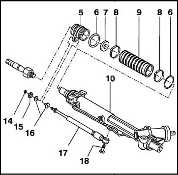
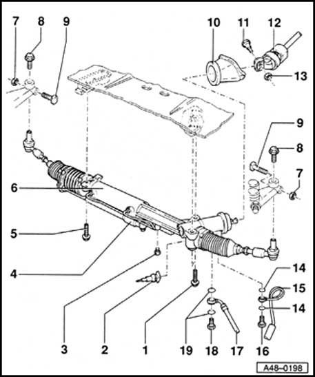
Overall Diagram:
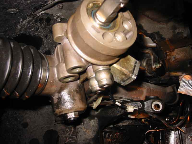
Deceivingly simple, yes? Maybe if the rest of the car wasn't built, yet.**
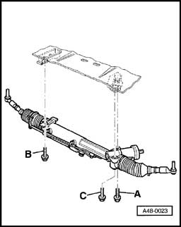
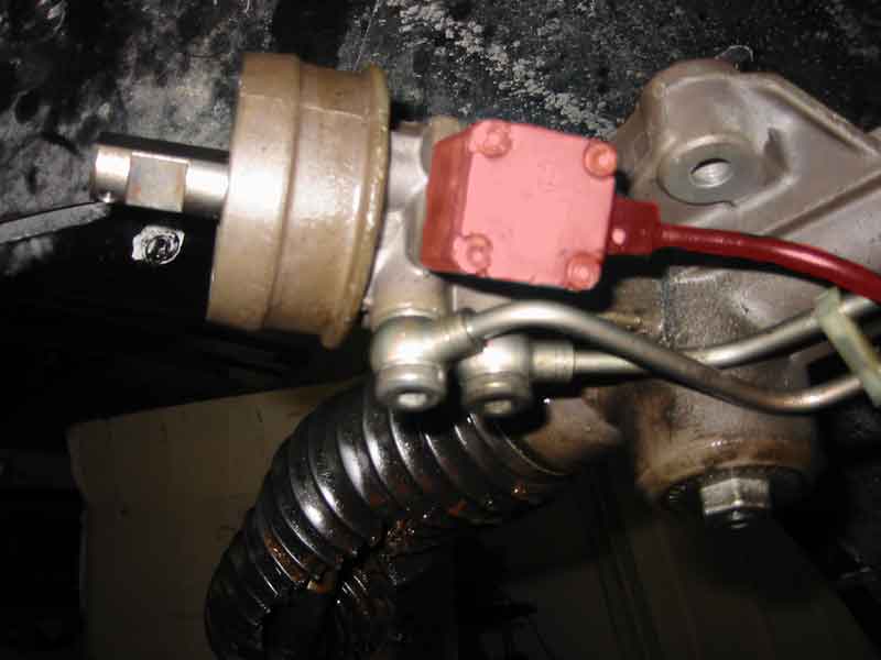
The three support bolts. Love them. Hate them.**
Procedure:
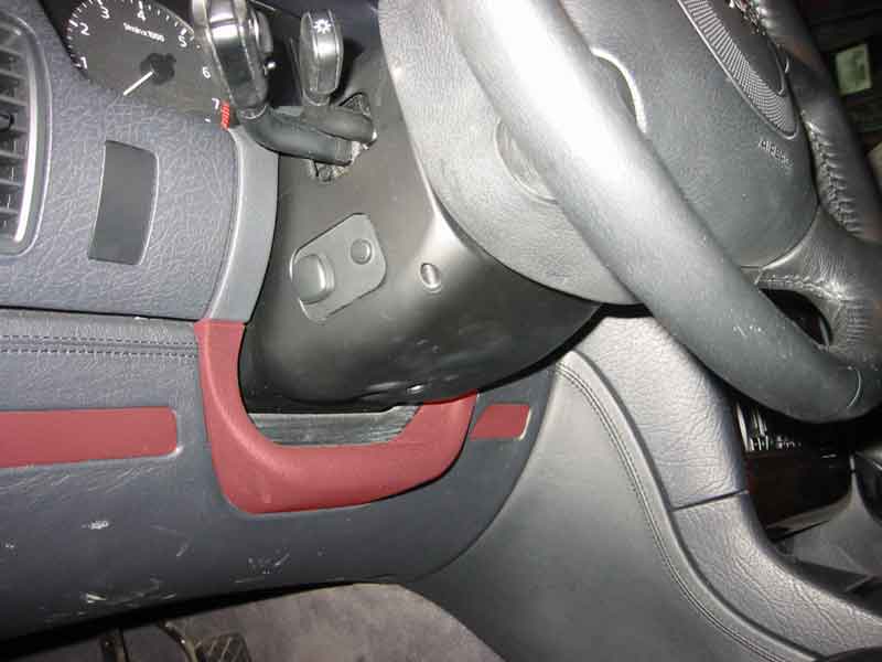
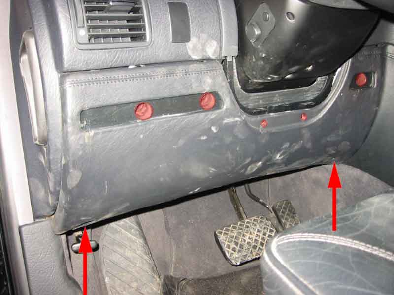
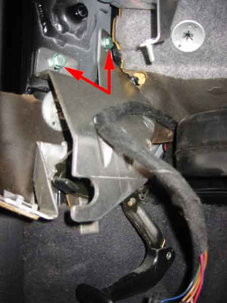
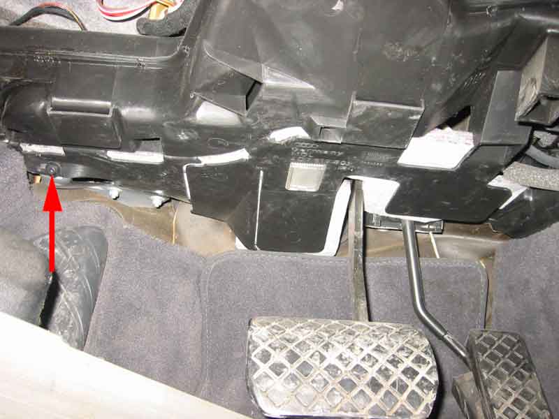
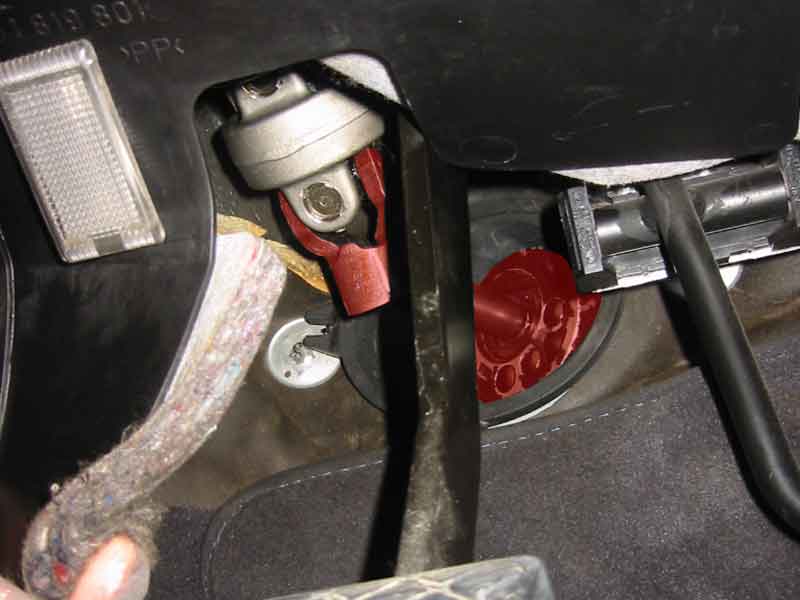
1. Disconnect steering u-joint.With car off, twist steering wheel until it locks as close to horizontal as possible.You can either cut away the flap above the brake pedal (kind extreme) on the underside of the steering link or move it enough out of the way to give you good access. For access, remove driver side lower trim and diagnostics port (use flat-head screwdriver to release the 3 locking tabs from front face of trim), twist left trim bracket out of way (only need to unscrew 2 closest bolts, leave far 3rd bolt in place to act as an axis), pull air duct slightly forward until it hits the bracket you just moved. Laying in the driver side foot well looking up, you should be able to get a good peep at the steering column u-joint.
After loosening and removing bolts, the joint can be pulled apart. However, try not to move the steering column more than necessary to move the linkage out of the way. Just a shade inwards towards the steering wheel and down towards the floor should give enough clearance to continue. Too far inwards and you could disengage the gears inside steering assembly, which is bad, very bad -- can you say new steering assembly?
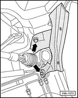
2. Pull rubber seal around the rack's rotary valve forward into the driver compartment.
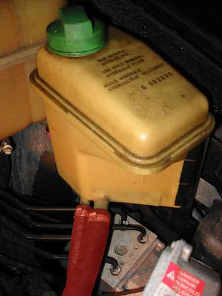
3. Clamp hoses connected to power steering fluid reservoir.
4. Lift car.Both sides if on blocks. Lift a little towards the car rear from the existing rubber reinforced lift points by the wheel well, so you can put the blocks on lift points. Be wary of brake lines (and suspension fluid lines, if applicable) near the lift points.
5. Remove both wheels.Not completely necessary, but makes life MUCH easier. And you'll need all the ease you can get.I noticed cold weather makes the plastic lug caps brittle. Why plastic lug caps instead of solid bolt heads?
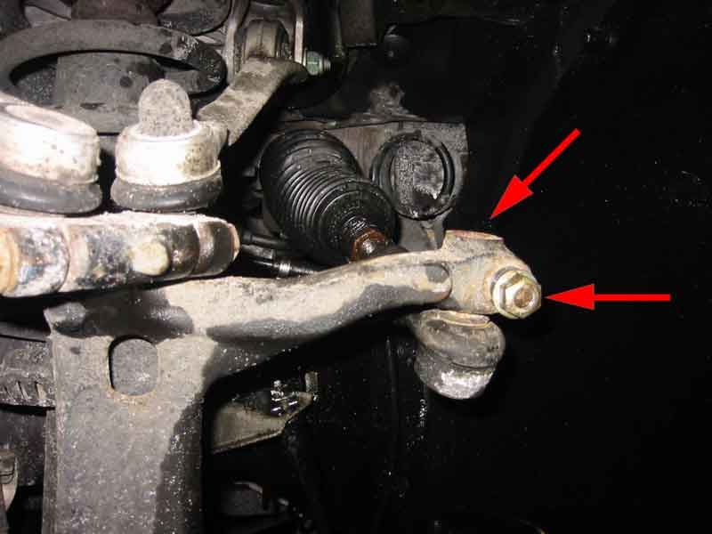
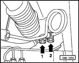
6. Disconnect both tie rod ends.
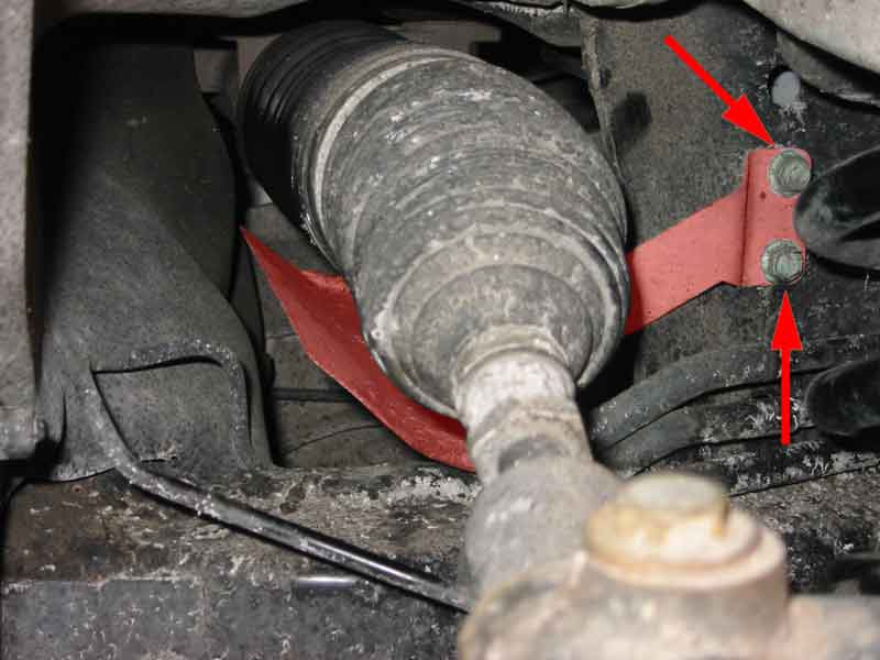
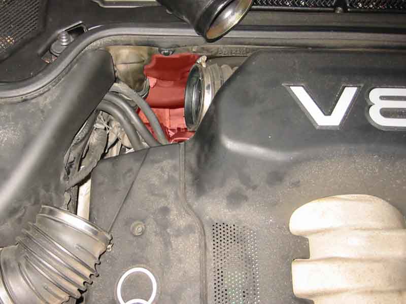
7. Remove heat shield on passenger side.
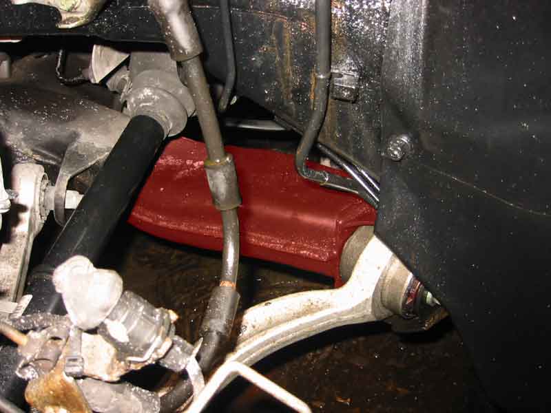
8. Remove foam insulating panel at inside rear of driver's side wheel well, around the rack's rotary valve.
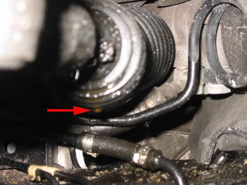
9. Disconnect high pressure fluid lines from rack by removing both banjo bolts.
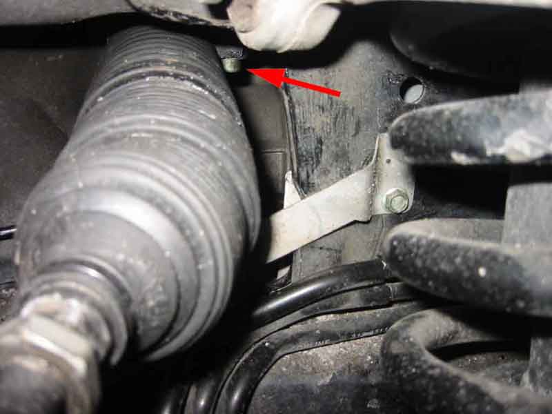
10. Loosen first rack support bolt to the car front, drivers side of the rack and pinion.
11. Loosen second rack support bolt.
12. Remove third rack support bolt.
13. Remove the previously loosened second rack support bolt.
14. Remove the previously loosened first rack support bolt.
15. Partially slide out rack.
16. Remove or Disconnect the Servotronic module.
17. Slide out rack all the way.Watch that you don't catch on cables and hoses.
18. Transfer the old steering damper to the new rack.
19. Center the new rack using the centering hole and centering bolt.I didn't have the special centering screw (VAG 1907), so I just watched through the centering hole for the "divot" on the rack shaft and then noted the length of the boot (the boot clamp to inner tie rod end on driver's side) and position of the u-joint steering stem at the centered state. There is a "cut-out" on the stem that allows a bolt to hold the u-joint, which should be pointing straight up when rack is centered.Or find another way to center the replacement steering rack after it is put in (see in later step).
Then transferred over the old screw plug (with lock-tite) from the old rack.
20. Slide in new rack part way to re-attach Servotronic module.Try not to pull or push on the tie rods while putting in new rack.If your replacement rack already has a Servotronic module connected, reconnect the cable to the connector and replace the wheel well liner. It might be a good idea to duct tape the cable to the wheel well to minimize cable vibration (noise).
If you need to transfer the old Servotronic module to the replacement rack, now is a good time to replace Servotronic's fluid strainer and o-rings. The o-rings go directly on the nipple and the strainer just goes into the receiving hole. I confess I only changed the strainer -- my new rack happened to come with one.
(See above for bolt/nut specs.)
21. Slide in new rack all the way.Try not to pull or push on the tie rods. The steering damper likes to catch on inner frame elements. May have to jiggle or lift it past them. Much easier with two people.
22. Attach and tighten (lock-tite) first support bolt.Assistant holding up rack makes it easier.
(See above for bolt/nut specs.)
23. Attach and tighten (lock-tite) second support bolt.Assistant holding up rack makes it easier. Also, assistant could hold the rachet head on the bolt through the wheel well, while you swing the handle through Satan's ***hole.
(See above for bolt/nut specs.)
24. Attach and tighten (lock-tite) third support bolt.Get it on the same way you got it off, from under the car. To make it easier to keep the bolt on the hex driver, tape the bolt head to the driver head enough that the bolt will stay on for the trip, but not so much it will not come off with a good pull.
(See above for bolt/nut specs.)
25. Re-tighten support bolts in the same order.
(See above for bolt/nut specs.)
26. Flush power steering pump of old fluid.Put return high pressure hose end (with J-shaped connection, not the coiled one) in bucket. Open fluid reservoir cap and release hose clamp from power steering fluid reservoir's lower return hose. This should slowly empty out the reservoir and return hoses of the old fluid into the bucket. Re-clamp return hose connected to the reservoir when finished.Fill reservoir with fluid. Put plastic bag over coiled high pressure hose end where it was disconnected from the rack to contain the high pressure fluid spew. Remove clamp from upper reservoir hose feeding power steering pump. Place bucket around plastic bag. Poke hole in bottom of plastic bag to drain sprayed fluid into bucket. Have assistant start car and turn off car after 1 second of run time. Repeat fill/purge until you've ejected about a liter of fluid. Re-clamp same upper hose from reservoir feeding power steering pump.
Even though the hoses aren't connected to the rack and this procedure could probably be done before putting the new rack in, I waited until after getting the new rack in to purge, because I wasn't certain what starting the car with a disconnected Servotronic module would do to the module, or the diagnostic computer. Figured starting the car with a connected module would be better.
27. Re-attach high pressure lines.Use new aluminum seals on both sides of both banjo bolts. Note that the part number for both lines may be the same, but the banjo bolts and seals are of DIFFERENT size. So, make sure the parts guy gives you 2 seals of each size.
(See above for bolt/nut specs.)
28. Re-attach foam barrier on driver's side.
(See above for bolt/nut specs.)
29. Re-attach heat shield on passenger side.Bolt first and then just reach in and "pop" the other end onto the steering damper piston housing.
(See above for bolt/nut specs.)
30. Push rubber seal back around the rack's rotary valve showing through the driver's foot compartment.Verify good positioning by looking through driver's side wheel well and adjust around neck of rotary valve if necessary.
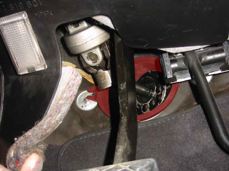
31. Verify centered steering rack and re-attach steering assembly's u-joint.There are a couple ways to verify that the steering rack is centered.The factory recommend way is with the special Audi centering screw (VAG 1907), which now has to be removed and replaced with the screw plug. As hard as it was to get to the support bolts, if you chose to go this route, I can only offer two words: good luck.
Or measure boot distance and compare to prior notes to approximate center steering position and check rack's u-joint connecting stem. The "cut-out" on the stem should be pointing up when rack is dead-straight. Use wrench to gently turn stem into proper position to mate with u-joint, since steering wheel never seems to lock in dead-straight position. Might be easier if steering lock is disengaged?
Or use a wrench or pliers to gently turn the rack's u-joint connecting stem from lock to lock, counting the number of revolutions. Reverse away from one of the lock positions half the total revolutions and you should be centered.
Or use your own method.
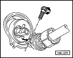
As you attach the u-joint bolt, note that because of the cam device in the u-joint bolt head, you'll have to take special steps in tightening:
(See above for bolt/nut specs.)
32. Tape-marker position of tie-rod position bolt on old rack and transfer to new rack.Try to be as accurate as possible, but don't sweat it too much -- you're going to have to get an alignment, regardless.
33. Re-attach tie rod to wheel bearing housing.The tie rod end stem that slips UPWARDS into the clamp of the wheel bearing housing has a "cut-out" portion. Align the cut-out portion of the stem so that it faces the horizontal bolt hole; it will be difficult to put the horizontal bolt in without this properly aligned. This is also a safety feature so that the tie rod will not slip out should the bolt loosen.Replace the self-locking nut. Notice that the horizontal bolt head has only one straight edge. Align this properly with the straight edge beveled into the back of the wheel bearing housing. Best to simply align the bolt head and press against the housing, the beveled edge will help the bolt remain still while you thread the self-locking nut.
(See above for bolt/nut specs.)
34. Clean.Learn to appreciate brake cleaner. WD-40 works well, too. But don't use it on surfaces that rely on friction, like bolt threads, tie rod stems, and the brake system.Clean and dry areas around pump, rack, and hoses to make leaks easier to spot.
35. Bleed steering system of air and check for leaks.The Bentley repair manual recommends the following procedure to bleed the power steering system:
36. Re-attach wheels.Don't forget the plastic lug caps.
37. Lower car.
38. Check again for leaks.Check the power steering system:
39. Test drive and check for leaks.Nothing high-performance, mind you. Your wheel alignment is most likely way outta whack and will compromise your ability to take sharp turns at high speed. Not to mention tread wear. Just drive around the block. Listen for additional odd noises. Feel for any additional odd vibrations.
40. Get alignment.Dealer charges about $150-170, depending on his mood. A respected mechanic once told me that Audi's (and other import luxury cars) have a complex alignment procedure that also requires tools that your local JiffyLube won't have. JiffyLube can set your steering wheel to point straight as your tires point straight, but there is more involved. Not sure what the "more involved" means, exactly... but I've been going to the dealer for the alignment, anyway.
41. Shower. Sleep.Great job! Have some beer. Admire how the gashes on your arms burn in the shower. Nothing a little more beer can't fix, eh?
** Diagrams and Illustrations from "Audi A8/S8: Official Factory Repair Manual on CD-ROM", Copyright Robert Bentley, Inc. and Audi of America, Inc., 2002
|