Background
To retrofit a Nav Plus unit to my 97 A8, I purchased a center console faceplate and rear bezel from an '00 A8 that I found in a junkyard. This included the switches at the top of the faceplate. Cost for the components was $280. I also had to purchase a climate control unit from an '00, which I purchased off www.ebay.de for $135 shipped.
These components are NOT like for like replacements, so I had to create interfaces for each. This was the most time consuming (engineering and modification) task of the whole project. If you would like to attempt this modification, I suggest that you get comfortable with everything you will be doing before starting.
Emergency Flasher Switch
The emergency flasher switch was the hardest to figure out of all switches. It works very different on the '00 versus the 97-99 model years. Differences include:
'00 switch has a built in relay to flash the left and right turn signal bus.
97-99 switch uses the J1 turn signal flasher relay (behind instrument cluster) to provide a flashing power supply and an additional J2 emergency flasher relay (in relay panel at passenger's foot) to connect the right and left turn signal buses together. This J2 emergency flasher relay is a two position relay. It does not "flash", it connects the left and right hand turn signal buses together so that the J1 relay can flash both at the same time.
The '00 switch has electroinics in it that input into other systems (not used on 97-99's).
Two jumpers will be used, one on the 97-99 switch to connect switched 12 VDC across the connector, another set of jumpers from the '00 switch to the existing emergency flasher J2 relay electrical connector.
The existing J2 Emergency flasher relay will be removed.
With this setup, if the ignition is on and the emergency flasher is used while a turn signal is on, that bus will not flash at the same rate as the emergency flasher, it will stay on constant or have very short flashes.
If you are interested in determining what you will be doing, I suggest that you print out the Bently wiring schematic for the 97-99 emergency flasher circuit and for the '00. It was very difficult for me to figure this out, took me about 5-6 hours to get it right. Or you can just follow the directions below and it should work for you. If it doesn't work correctly the first time, then triple check your wiring and ensure the spade terminals are all tight and installed correctly.
The emergency flasher will work by inputting unswitched power into them, and using the internal relay and push button switch, energize the flashing circuit. The output of the "flashing bus" will then be routed through new wires to the existing J2 emergency flasher relay in the passeneger footwell relay panel. The J2 emergency flasher will be removed, and the wires attached to the "goes out" of the relay. This is actually a connection point for the left and right hand turn signal bus. This will allow it to power the left and right hand turn signal buses (A5 and A6) at the same time. The J2 relay will no longer be needed and provides a very convienient connection point to the turn signal buses.
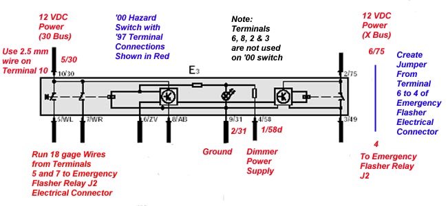
The following is the schematic for the '00 emergency flasher switch/relay. Note that the only termianls that will be used are 1, 2, 5, 7 and 10. No wires will be attached to terminals 2, 3, 6 or 8.
Schematic for retrofitting '00 and Newer Emergency Flasher Switch
Install the 2.5mm diameter factory wire into terminal 10 of the female electrical connector. Use 1.0mm diameter wires for terminals 1, 2, 5 & 7. Run a jumper from the 97-99 emergency flasher switch electrical connector to the following connections:
5 to 10 (2.5mm diameter wire), unswitched 12 VDC
1 to 4 (1.0mm diameter wire), dimmer power supply
2 to 9 (1.0mm diameter wire), ground
Insert two 1.0mm diameter wires into 5 and 7, these will be connected to new 18 gage wires run down to the J2 emergency flasher relay electrical connector
Create a short jumper wire with two spade clips and connect it between terminals 6 and 4 of the 97-99 emergency flasher switch electrical connector. This jumps switched 12 VDC across this contacts and provides switched power to the J1 turn signal relay. Without this jumper, the turn signals will not work. Do not connect these wires to the '00 switch.
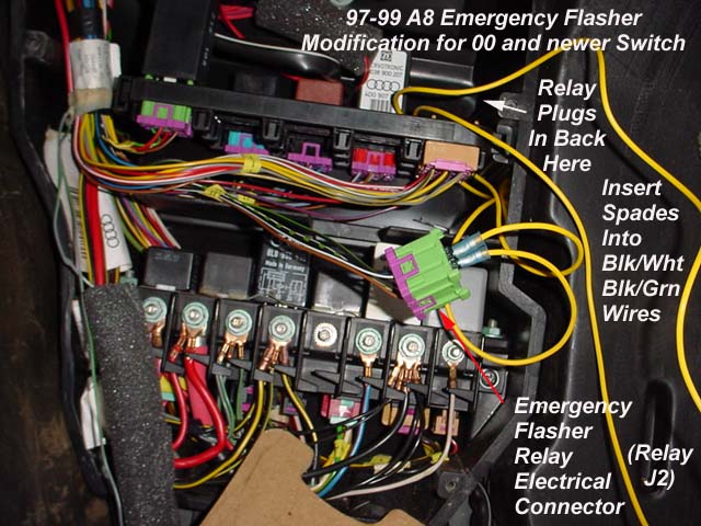
Run jumper wires from the emergency flasher switch terminals 5 and 7 to the J2 relay electrical connector. The electrical connector is green, and the most aft and outboard connector in the block. It is positioned behind the brown electrical connector in the right hand of the photo. Remove the relay (leave uninstalled), remove the connector from the rack, insert the spade connectors into the brown/white and brown/green wires and reinstall in rack.