Installing a Bluetooth Kit Handsfree
Phone Kit in an Audi D3 A8
By Paul Waterloo
Placing the Telematics Module in/out of Service Mode
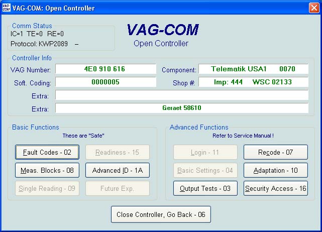
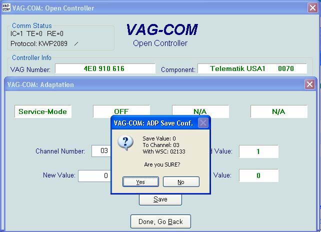
Place the Telematics Module into service mode. This is accomplished by hooking up VAG-COM and typing in the address “75”.
Once at the Telematics module, choose “Adaptation – 10”
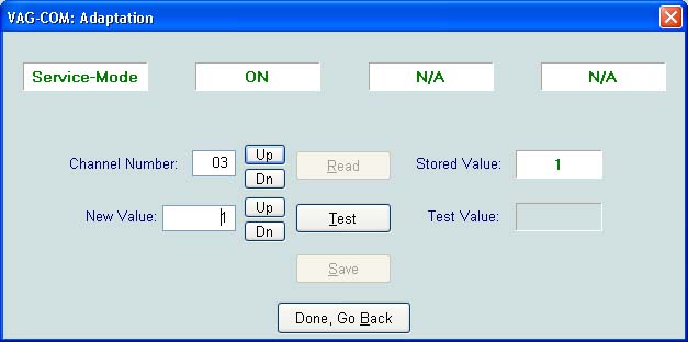
Click up to channel 3 and click “Up” in the box to the right of the “Test” button. Once it is set to “1”, click “Test”, then click “Save”, accept and it will place the module in service mode. To verify, close the controller, reopen, go to “Adaptation -10”, channel 3 and verify it is in service mode.
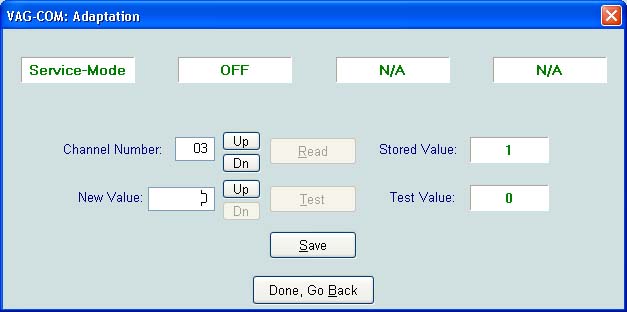
To take the module out of service mode, reverse the above procedure using “0” for value.
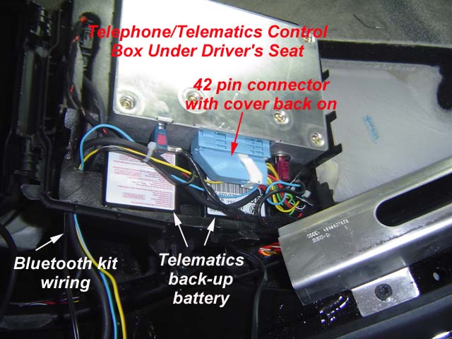
Remove the Telematics Box
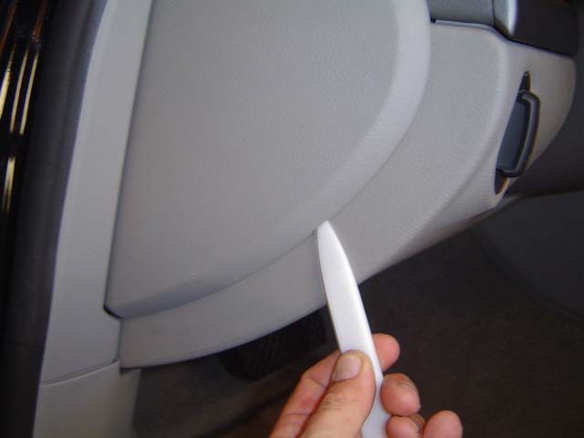
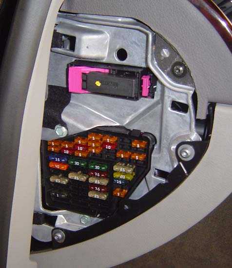
Remove the left hand side fuse panel. This is accomplished by popping the cover off with a trim stick. Once complete, REMOVE fuse SB13, which is the unswitched power to the Telematics/telephone box before starting. This will prevent inadvertent grounding of the power supply during installation.
CAUTION: Remove fuse SB13 (labeled 13), which is the unswitched power to the Telematics/telephone box before starting. This will prevent inadvertent grounding of the power supply.
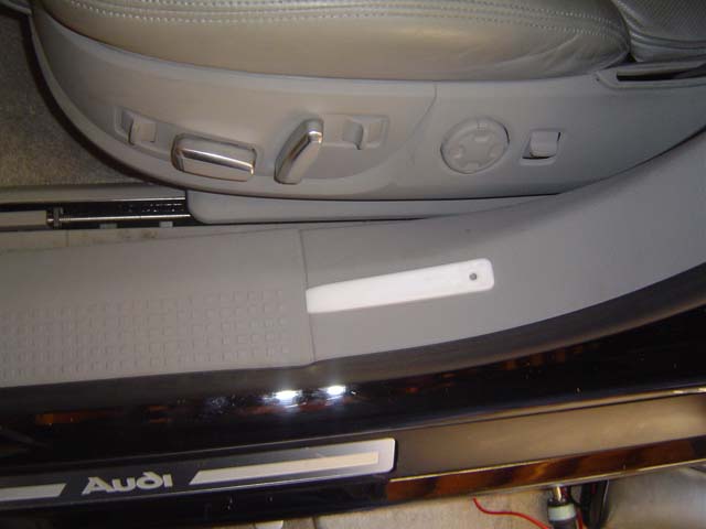
Remove the door kick panel trim by prying it up on the aft portion of it and unclipping it, then pull the vertical portion out, it just clips out.
Remove the driver's side floor mat.
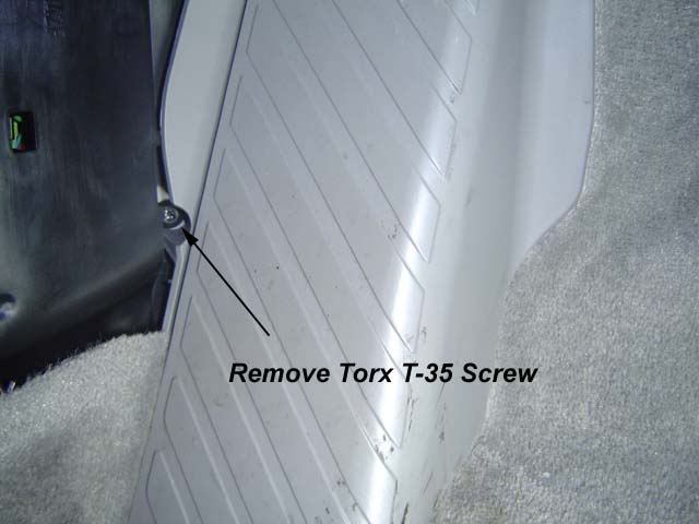
Using a Torx T-35 screwdriver, remove the screw that holds the left foot rest in place. Be careful when removing the screw not to drop it down into the floor board.
Remove the left foot rest. This is accomplished by pulling on it, it has two additional clips on the back that just pull out. Be gentle but firm, it should not break, just click out.
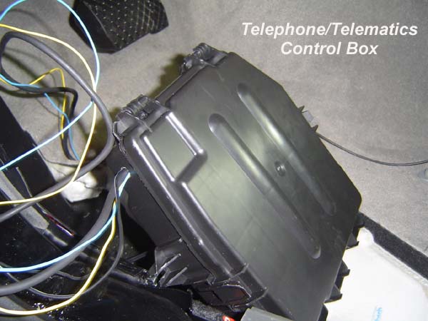
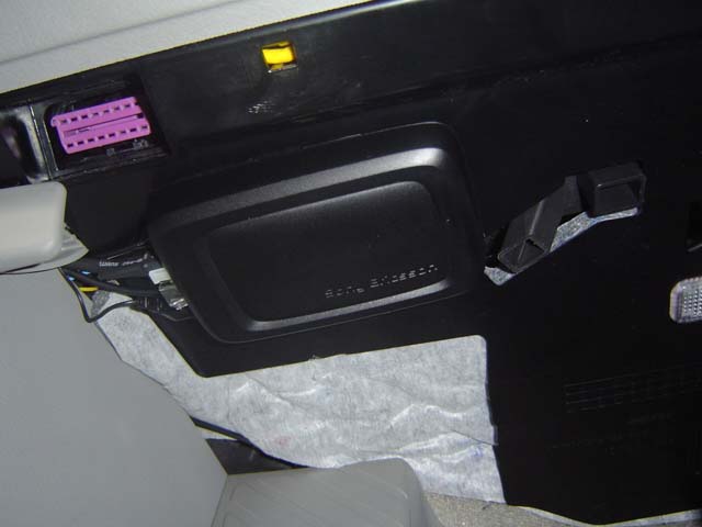
Pull carpet up from front left corner and you'll see the Telematics box. To remove the Telematics box, it's easiest to have somebody else help you and pull the carpet back from the passenger seat and hold it back while it is pulled out.
There are small studs that it sits on which must be cleared. There are no nuts on these studs, just the stud needs to be cleared. Pull the box out.
Open the Telematics box cover, it has four clips on the sides and aft end, and a hinge on the forward end of the box. Pull the Telematics box out of its foam covering.
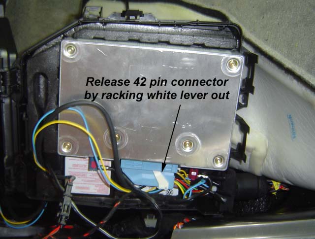
Disconnect the 42 pin connector from the Telematics box. To remove the connector, it must be racked out using the small white lever on the connector. Just release the white lever, rotate it, the connector will pull out.
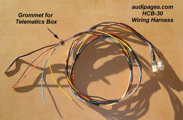
Remove two antenna wires (bordeaux and blue in color). Remove wiring from box by taking large rubber grommet out of entrance to box. Bring box to a suitable work location.
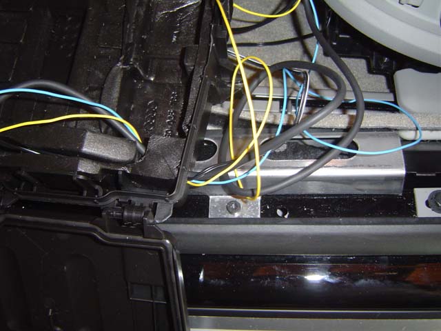
On the forward left hand side of the box, drill a hole that is approximately 3/8" diameter or slightly larger. This hole should be aligned with the back up battery wire cut out on the foam padding. It should pierce through the foam padding to the wiring channel.
Place the supplied wiring grommet in the hole and thread the wiring harness through the grommet.
Note that the above pictures show a slightly different
wiring harness than audipages.com supplies.
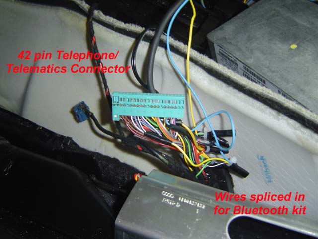
Connecting up the Wiring for the Kit
When wiring up the kit, cut the wires in the supplied wiring harness to the correct length. The Bluetooth brain box will be mounted just adjacent to the VAG-COM port and the wiring will be run down the factory wiring run. Leave approximately 6" of wire length at the end of the run at the floor board before the harness goes into the Telematics box.
After the wiring is run into the Telematics box, trim it to length (removing the electrical tape as required) before making up and soldering connections.
The following will be hooked up, in the following order:
B Pillar Speaker (+)
B Pillar Speaker (-)
Phone Mute
Switched 12 VDC
Unswitched 12 VDC
Ground
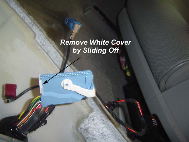
Remove Cover from 42 Pin Connector
Remove the cover from the 42 pin connector by sliding the end cap off. Once the end cap is removed, slide the 42 pin insert out of the connector housing.
B Pillar Phone Speaker
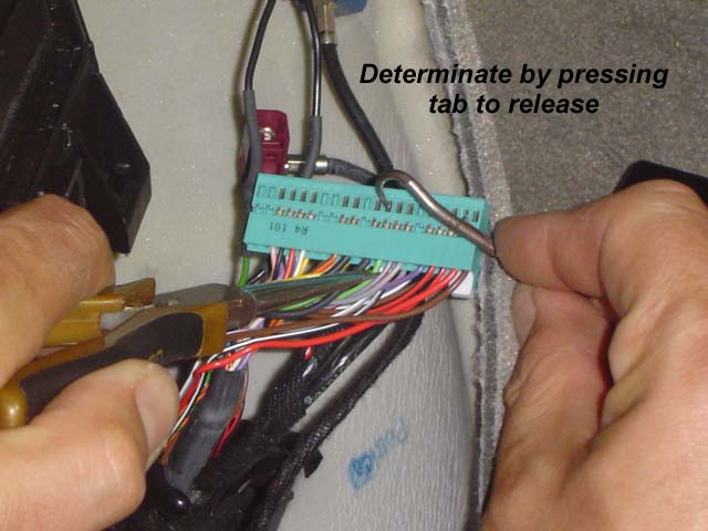
Determinate the B pillar phone speaker wires by using the supplied pick tool. Press down on the tab as shown below and push with the tool/pull with your fingers and the B pillar speaker wires will come out.
Remove wires from pin 11 (green) and pin 32 (black).
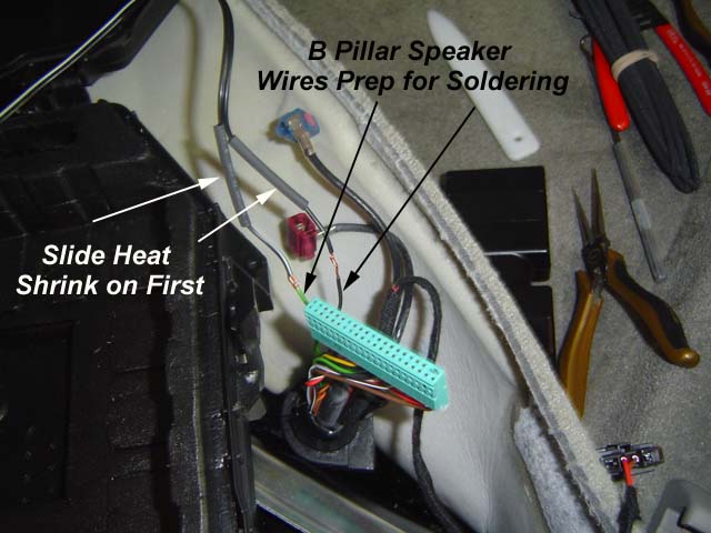
Once removed, you will be cutting the ends off these wires and attaching them to the Bluetooth speaker output wires (black and black/white wires). To connect, strip both wires back, place a piece of supplied heat shrink tubing over the speaker wires, then twist the following:
Green, terminal 11 to Black/White, Bluetooth kit speaker (+) wire
Black, terminal 32 to Black Bluetooth kit speaker (-) wire
Solder the two together by tinning the soldering iron, heating the joint, and flowing solder in. Let cool, put the heat shrink over the connections and heat shrink.
Power, Ground and Mute
For the power (switched and unswitched), ground and phone mute, the wires will be determinated as above, but then a jumper installed and new wires piggy backed on the existing wires.
The wiring diagram is provided an additional document.
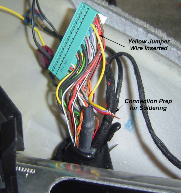
To connect the wires, determinate the wire in the first column. Insert a supplied yellow wire jumper in the 42 pin connector. Make sure it's trimmed to the correct length. It will have to clear the 42 pin connector, but don't make it too long. Before trimming, consider putting the connector cover back on to see what you will be doing.
Once the wire is trimmed, strip the end. Cut connector off wire end of removed wire. Strip back. Strip the Bluetooth kit wire to be connected.
Twist all wires required for connection as shown:
Connection prep for soldering. NOTE: Violet is NOT used for your kit. Follow wiring tables.
After the wires are soldered, place a piece of heat shrink over the connection and heat to shrink. Tape connections as required. It is recommended to use electrical tape only versus tie wraps so that wires do not get cut.
Complete all four connections in accordance with wiring table.
Replace the 42 pin connector housing on the connector.
Reconnect the control module to the 42 pin connector and the two antenna wires. Route the Bluetooth kit wiring in the box smartly.
Plug in all Bluetooth kit components to brain (wiring harness, speaker harness, mic, remote button control and speaker). Reinstall fuse SB13. Turn on ignition and test kit. If it works properly, turn off ignition and continue. If not, troubleshoot the problem or contact audipages.com.
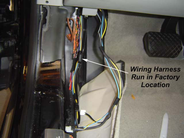
Run the wiring in the factory location by unclipping the clips (two or three) and run the wiring harness along with the factory harness. No need to tape or tie wrap it in.
Run the wiring harness in factory location. NOTE: this harness was pulled back significantly from the shown location in the picture above. It much be much shorter up near the VAG-COM connector.
Size wiring harness so it will support putting the Bluetooth brain box here. It should have very little slack going into the factory wiring harness at top and about 6" extra at the bottom before going into the Telematics box.
Reclip the factory wiring cover. This is not easy sometimes, use a pair of needle nose pliers to help you reclip it if required.
Close the Telematics box and reinstall in location. Put carpet down.
Mounting the Bluetooth Brain Box
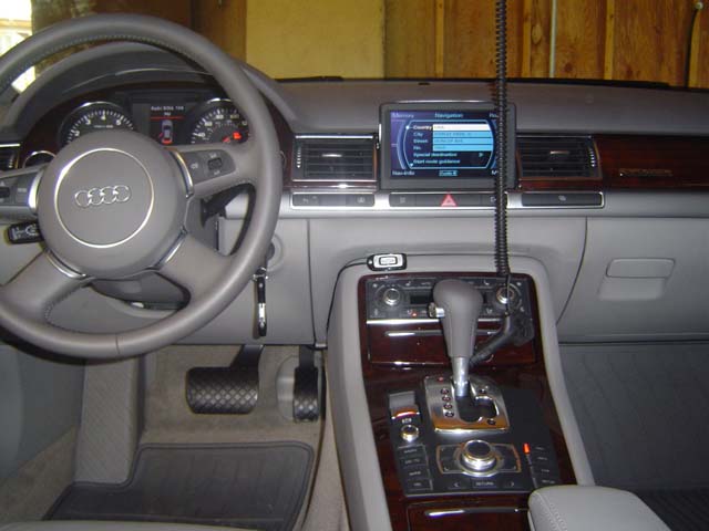
Using the supplied velcro in the HCB-30 kit, secure HCB-30 brain box just forward of the VAG-COM plug as shown in the picture above. The end with the wire connections should be pointing outboard.
Routing the Microphone Wire
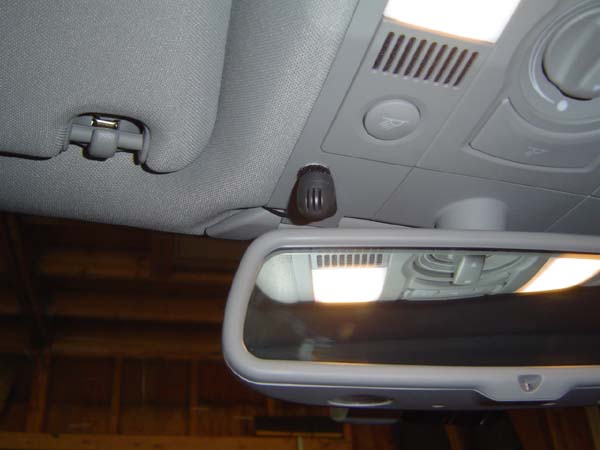
The microphone will be mounted on the sunroof control panel. Using the supplied velcro on the back of the microphone, attach it to the sunroof control panel.
Tuck it up behind the middle sun visor, and then into the headliner where it meets the windshield.
NOTE: The wire is not thick enough to stay between the headliner and the windshield. This is cured by wrapping a few turns of electrical tape around the wire to increase its diameter. Do this every 3"-4". Then push it up in the headliner with the supplied plastic spatula. Continue running the wire along the driver's side A pillar, adding electrical tape as required.
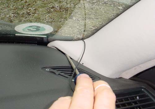
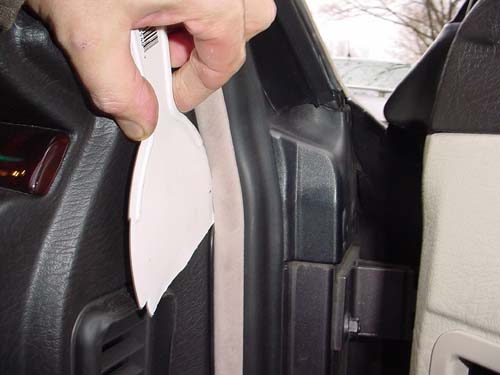
Using the plastic spatula, run it all the way down the A pillar to the base of the windshield. Then run it between the A pillar trim and the dash panel. Run it down along door trim out, behind the fuse panel cover (panel must be removed). The following pictures are on the passenger side of a D2 A8, but it is the same concept. There is NO need to use a screwdriver or have to lift the A pillar trim up as shown below.
D2 A8 passenger side shown, but run the mic wire in the same fashion on the driver's side.
Once the mic wire has been run down to the HCB-30 brain box, plug it in.
Routing the Touch Pad Wire
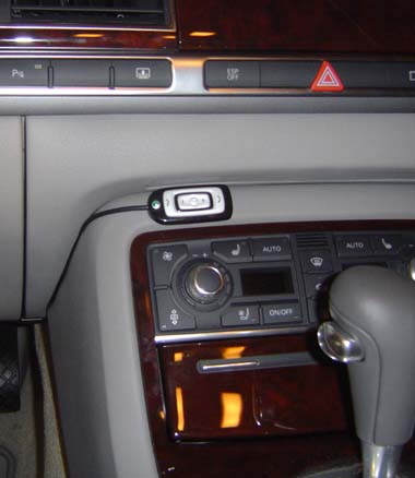
The HCB-30 touch pad can be mounted where ever you desire. One place is to mount it just above the driver's HVAC control knob. To do so, tape the touch pad to the dash with the attached tape on the back of the unit. Using the trim stick, push the wire between the console and lower left hand dash panel. Route over to the HCB-30 brain box, tape up slack in cable and plug in.
Take the Telematics Unit Out of Service Mode
Take the Telematics unit out of service mode in accordance with above instructions.
Reinstall Driver's Side Trim
When all steps above are completed and tested satisfactorily, replace trim in reverse order of removal.
Clip left foot rest in place and secure Torx T-35 screw. Replace driver's door trim kick piece by using only hands to reinstall, vertical section first, horizontal section second, hit down with hands to clip in place.
Installation of Console Mount, Antenna and Wiring
The following steps outline installation of the phone console mount, antenna and phone charger power supply.
Remove the Armrest Cover
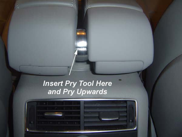
Split the armrest cover plate with a trim stick or a screwdriver wrapped in electrical tape. From the back seat, just pop it in the split and pry it upwards. Move around front and pull it off the armrest, working the base gasket down.
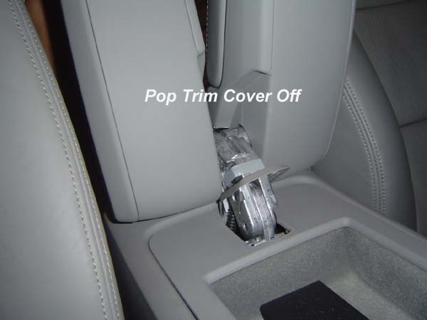
From the rear seat, using a trim stick or screwdriver tapped with electrical tape, gently pry the trim cover apart. Then move to the front seat and completely remove it.
From the front seat, remove the entire trim cover. Be gentle with the trim gasket.
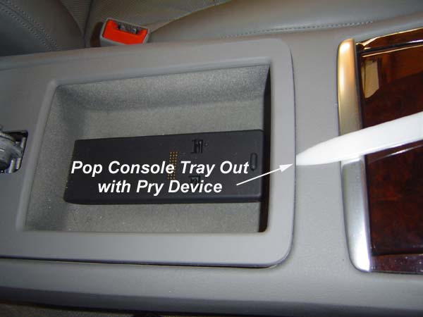
Unlatch Center Armrest Tray
Using a trim stick or screwdriver wrapped in electrical tape, pop the front of the center armrest tray.
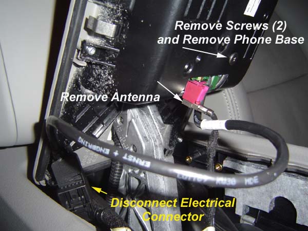
Disconnect Wiring and Phone Base
1. Unplug the bordeaux antenna plug.
2. Disconnect the phone base electrical connector by releasing the tab on it.
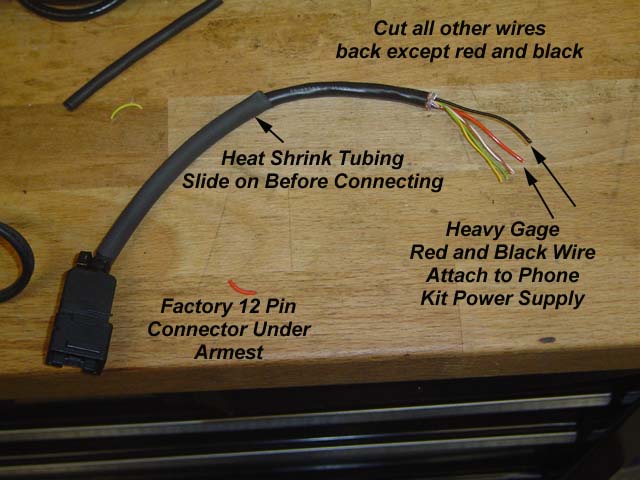
NOTE: If you did not send in your phone base for modification, you will need to cut the conductor between the factory 12 pin connector and the phone base. Follow the supplied wiring diagram instructions for stripping and connecting the wires.
Cut conductor between factory 12 pin connector and phone base.
Use the heavy gage red and black to power the phone charger.
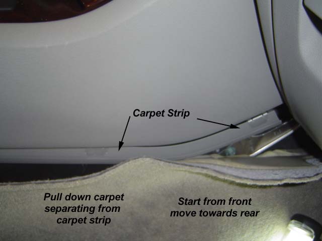
Detaching the Right Hand Carpet
The carpet on the right hand side of the console will be detached to route the wires from the base to under the armrest. The carpet system is very easy, once it is removed, it is easy to determine how it goes back on.
NOTE: It is easiest to determine where to place the carpet strip back on the carpet by MARKING IT FIRST. Using a pen or marker, mark the carpet strip and carpet next to the passenger seat where no one will see after assembly. This will allow you to position the carpet strip on the carpet during installation properly without a lot of trial and error.
Start near the glove box (forward) and pull down on the carpet, separating it from the carpet strip. The carpet will pull out of the strip. Remove the carpet until it ends, which is about 2/3rd's towards the rear of the passenger seat. Another piece of carpet starts there, do not remove that piece.
Pull down on carpet, it will separate from carpet strip. After the carpet is removed, pull the carpet strip down from the console. The carpet strip is then attached to the carpet before reinsertion into the console. It is easy to figure out once you see it removed.
Remove the carpet strip from the console by pulling down on it. There is a small clip that holds and front and rear carpet strip together, be careful with it and separate the two pieces, if it breaks, it's no big deal, it is not really needed.
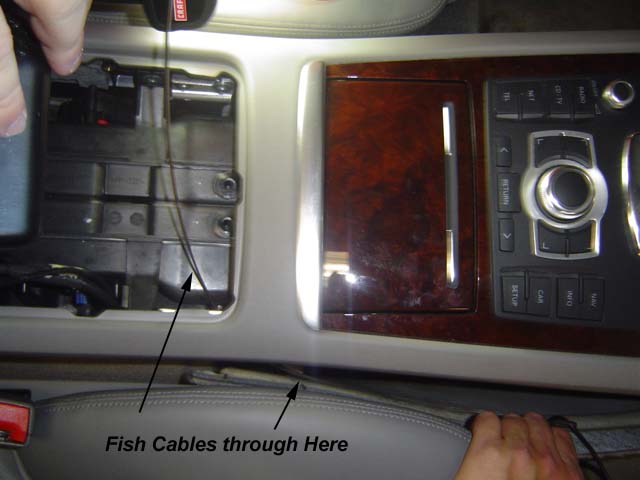
Run the Phone Power Supply Wires and Antenna
Using a hanger that has been cut or other suitable device, insert the hanger from top or bottom as required and pull through the phone base power supply wires and the antenna wire.
NOTE: These cables have soldered connections at the power supply and at the green antenna connection. DO NOT pull these connections through the console. Use the other end of the wire and pull through the correct way.
1. Pull the antenna wire from the armrest area through the console to adjacent to the passenger seat.
2. Pull the phone cradle power supply wires from the passenger compartment through to the armrest area.
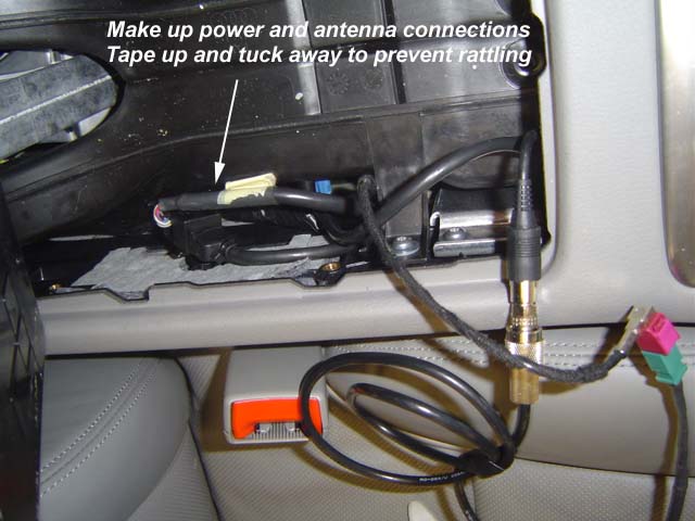
After the wires are fished through, connect the black to black and red to red as in the soldering procedure above and the wiring diagram. If you have a Motorola kit, connect the blue to blue.
Make connections to 12 pin connector if you did not send in your phone base for modification.
Connect the antenna wiring to the factory wiring.
Plug in 12 pin connector to factory wiring harness and plug phone into cradle to ensure it charges. If it doesn't, check all connections are made and that Fuse SB13 has been reinstalled. If it is not charging, troubleshoot or contact audipages.com.
Tape up the extra wire and tuck away inside the console so it won't rattle.
Mounting the Console Mount and Reassembling
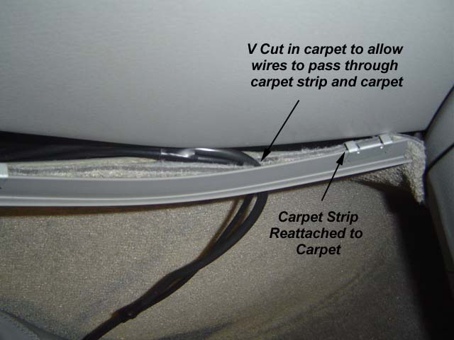
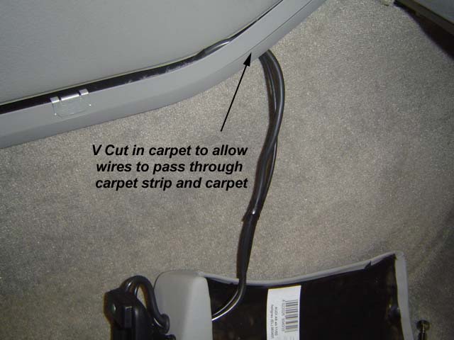
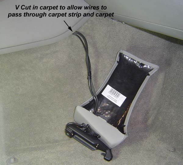
Position the Kuda console mount on the console and test fit. Cut a "V" notch out of the carpet where the phone cables will be hidden by the Kuda console mount. You have to cut not only a slit, but have to cut a "V" or "U" notch for the wires to pass through. Start small and work until it is big enough. The carpet strip must fit back over the top of the carpet.
After the carpet has been cut and properly fitted, attach the carpet strip back on the carpet using the markings you made prior to removal. If you did not make markings, look between the seat and console and fit the carpet strip to the carpet.
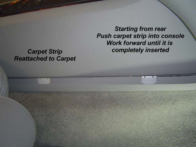
NOTE: Fit the carpet strip from rear to front.
Position the carpet strip on the center console. Push the carpet and carpet strip up and into the console from rear to front until it completely engages.
After the carpet strip is in place, mount the Kuda console mount.
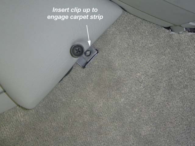
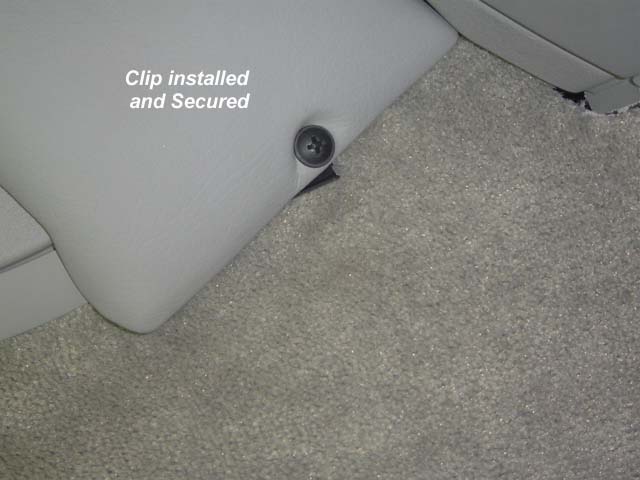
To mount it, put it place, and following the Kuda instructions, place the speed fastner on the clip. Slide the clip behind the console mount and position it so that it engages the carpet strip. Screw the supplied screw in. Do not over tighten.