Motorola V60 Hands Free Kit Installation
By Paul Waterloo
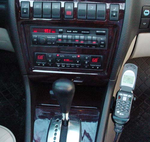
Installing a 3 Watt Hands Free Kit in the A8
Like most A8 owners, I have a digital portable cell phone. Recently changing it to the V60, I wanted to install a hands free kit in my car.
However, I wanted to integrate it into the Audi supplied phone components in the car. All A8's came pre wired for a phone from the factory. This included a wiring harness, a cell antenna integrated into the antenna shaft, a speaker between the front and rear door (B pillar) at hip level, a microphone in the sunroof control area and a radio muting system that was integrated into the system.
The cars that were delivered with phones came with analog phones, which are essentially now obsolete in the U.S. and Europe. Therefore, owners are stuck with using their hand held phones in their car. This can be complicated by cars that have the hot weather package, as the glass film does not allow the passage of cell phone frequencies easily.
A hands free 3 watt system with external antenna can help solve those problems. Plus if you live in New York, it is illegal not to talk hands free.
If you have a Nokia phone or are interested in installing any type of hands free kit, check the following two articles out. The majority of all of these procedures (including this one for the V60) apply to any type aftermarket hands free kit.
Using Existing Factory Phone Components
All U.S. bound A8's came prewired from the factory with the following components:
Wiring harness
Cell antenna integrated into the antenna shaft
Speaker between the front and rear door at hip level
Microphone built into sunroof control area
Radio muting system into the phone system
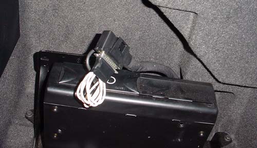
The car is prewired with all the conductors, power supplies, grounds, radio mute, etc. from the factory. It is all terminated in the trunk at the 25 pin connector (DB25) behind the CD player. If you car didn't come with a phone, just stick your hand behind the CD player and you'll find it.
D25 connector in trunk behind CD player with custom D25 male jumper installed.
Instead of hard wiring all the components, you can use the pre-installed wiring harness. This includes the DB25 connector in the trunk and the RJ-45 connector in the center console.
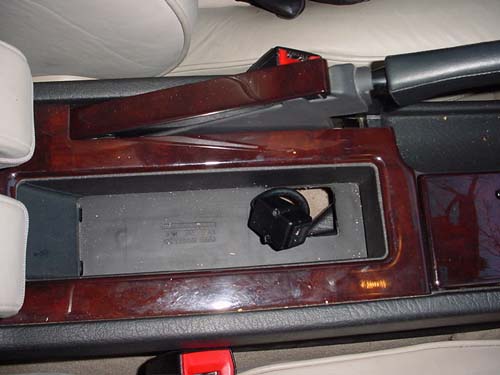
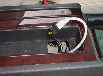
RJ-45 connector in center console. All A8's came with this connector prewired from the factory.
The DB25 connector has all the connections that is needed for the phone installation. 8 of the 25 pins are wired to the 8 pin, RJ-45 connector in the center console. So there is no need to run new wires from the trunk to the center console, they are already in place! For this installation, these conductors will be used to run the switched and unswitched power, ground, speaker and radio mute function.
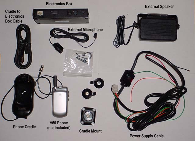
The V60 Hands Free Kit
I bought my V60 hands free kit off ebay, it is Motorola part number S9563. It cost $110.
Motorola V60 hands free kit S9563. Not all parts are used for this installation.
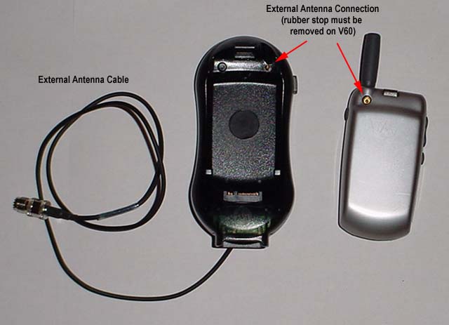
V60 phone and cradle included with kit. The rubber stop from the back of the phone must be removed to allow for proper fit in the cradle and to activate the external antenna.
The kit includes an external speaker, but it is not used for this installation. The built in speaker between the front and rear driver's door is used. However, the wiring harness for the speaker from the kit IS USED. It will require the speaker wire to be cut between the connector to the electronics box and the speaker.
All of the wiring from the electronics box (switched and unswitched power, ground, speaker and radio mute) will be routed through a RJ-45 patch cable to the RJ-45 connector in the center console which is connected to the DB25 pin in the trunk (via factory wiring). The female DB25 connector will require a custom DB25 male jumper installed to finish the wiring.
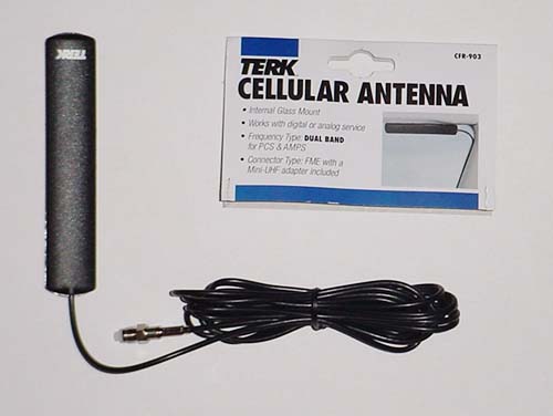
Also required is an external antenna for the phone. Since my car has an aftermarket automatic mast antenna installed, my car no longer had the built in cell antenna. I installed a Terk CFR-903 antenna. Visit Terk's web site. To use the stock antenna mounted in the rear fender, an antenna wire will need to be pulled from the interior to the trunk. The connector for the antenna is at the DB25 connector in the trunk. However, this could be a good excuse to get rid of that ugly stock antenna and replace it with an electric antenna. Then all that will be need is the Terk antenna in the front window. If you have the hot weather package on your car, you may need an external antenna.
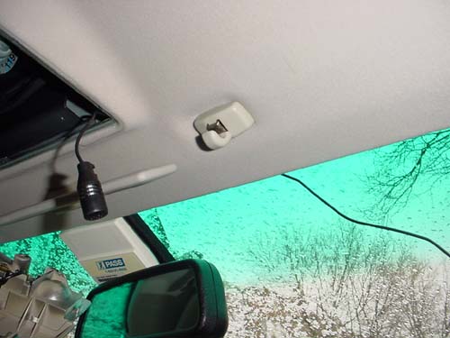
Terk CFR-903 antenna. This product is about $15 and found on the internet. It is 4" x 1/2" and mounts inside the front window. Once it is installed just under the headliner, it is not visible from the inside or outside.
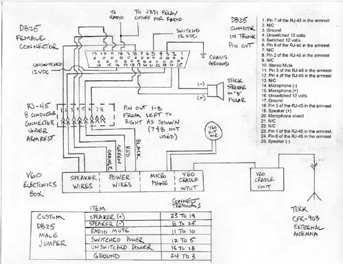
Wiring Diagram
The following is a wiring diagram to connect the hands free kit to the RJ-45 connector in the center console and the custom DB25 male jumper to make the final connections. Don't be scared by it. you don't even have to understand it. All you will need to do is to make a custom D25 male jumper (documented at the bottom of the diagram) and connect a network cable with a RJ-45 to the V60 electronics box wiring. This diagram is for people who want to understand what is happening with their installed wiring.
I believe all Audi's (A4's, A6's and A8's) with bose radio systems have this exact same pin set up. If you have an A4 or A6, check the Bently, if the wiring diagram is the same, this entire procedure is applicable to your car.
Click on the diagram above for a printable PDF version. Print it out so you can understand the custom DB25 male jumper.
Custom DB25 Male Jumper
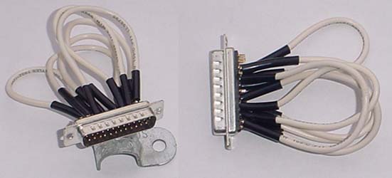
To understand the DB25 male jumper, you will first need to understand what you are doing. The DB25 female pin in the trunk has everything already wired into it. All the "goes in" and "goes out" that you will need. However, since there is nothing connected to it, a male jumper connector will be required to connect six sets of wires. They will just jump the circuit from one pin to another. Here's a picture of what you'll be making:
Custom DB25 male jumper. It's nothing more than a DB25 male connector with solder pots. Cut six pieces of wire and solder them to the terminals shown in the wiring diagram above. All it does it jump one terminal back to another. Note the heat shrink tubing, this must be slid on the wire before soldering the connections.
To make the DB25 male jumper, you'll need to pick one up with solder pot connections on the back. You can find the connectors at a computer store for $5 or less. Then cut six pieces of 18 gage wire about 6" long. Strip each end, slide two pieces of heat shrink tubing on the wire, and tin the wire on each end.
Tin connections 3, 5, 8, 10, 11, 12, 16, 18, 19, 23, 24 and 25 on the DB25 male connector.
Solder the wires to the applicable terminals as shown at the bottom of the wiring diagram above. Slide the heat shrink tubing down and using a heat source, shrink it. Using a test light or multimeter, check that you've connected the right terminals! Once it's complete, you can install it in the female connector.
Custom DB25 male jumper installed in female DB25 connector in trunk.
Installation
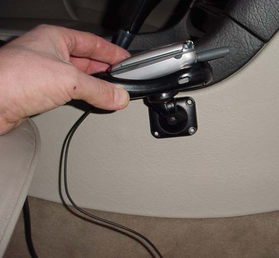
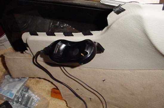
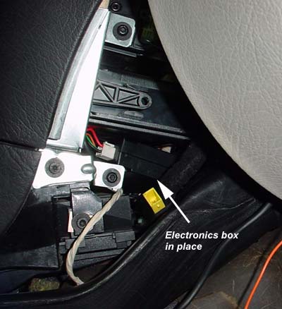
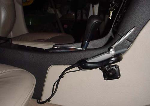
To install the unit, you will need to determine mounting position. I mounted mine on the right hand side of the center console just outboard of the gear shifter. When determining a location, ensure you open the glove box, after I finished my install, I determined that the glove box door contacts the antenna on the V60 phone. With it removed, it can fully open.
Determine mounting location of the V60 cradle. Shown are the mounting pieces that come with hands free kit. They allow for mounting in many positions. Open the glove box when positioning the unit and check for interference. Mark the four holes for drilling later.
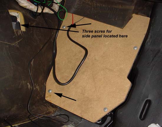
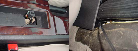
Remove the side panel. The carpet and side panel are all one piece. First, remove the floor mat, then the floor carpet. You'll find a hole in the side panel carpet for a screwdriver. Remove the one screw that goes into the transmission tunnel. The other two screws are phillips head that hold the cover on the relay panel. The following picture shows where the screws are located.
Put the passenger seat all the way back. Once you have removed the screws, slide the panel forward and lift the carpet up and over the seat track. The tab on the panel needs to clear the black trim by pushing the panel forward. Once it is clear, lift it up and over the inboard seat track and pull the bottom out towards the door. The front will then follow. Bring it out bottom first, disengage the top, then pull the top out.
Once the panel is removed, drill the panel and mount the phone cradle using the supplied nuts and bolts.
Panel drilled and phone cradle mounted. Note the tab on the back side of the panel that engages the black trim shown in the picture above.
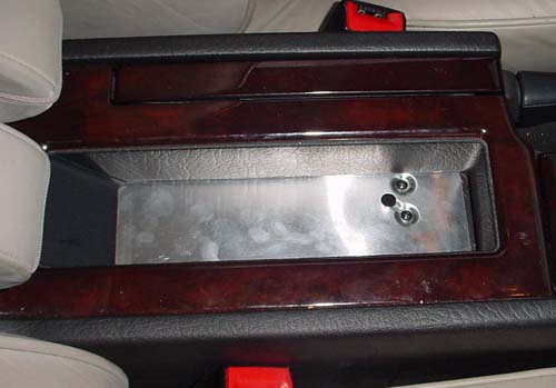
Next step is to run the RJ-45 cable from the center console up to the radio area. Remove the small piece of carpet in the center console by using a screwdriver to get it started, it pulls right up. You will see the metal plate under carpet, remove the two screws. Pull it up and the factory installed RJ-45 is right there.
Factory installed RJ-45 connector under metal plate.
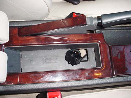
Using a RJ-45 computer network cable at least 5 feet long, cut the connector off one end. Take a hanger or wire puller (what I used) and slide it in from forward of the passenger seat, under the HVAC ducts and snake it around until it is seen in the hole in the console. Attach the RJ-45 cable (stripped wire side) to it and pull the cable through. DO NOT CONNECT THE RJ-45 CABLE AT THIS TIME!
Wire puller used to snake through center console. Use a wire puller and run it under HVAC ducts up through the console. Pull RJ-45 cable through. DO NOT CONNECT THE RJ-45 CABLE AT THIS TIME!
You'll want to route the wire first through the console (see step above) before you strip it. Once you strip it, you'll be connecting the following (be sure to verify these color/positions on your network wire, all cables might not be the same). The speaker wire will need to be cut at the speaker so it can be connected to the RJ-45 cable.
Black speaker wire - connect to - solid brown wire
Black/white speaker wire - connect to - brown/white wire
Orange radio mute wire - connect to - green wire
Green switched power wire - connect to - white/blue wire
Red unswitched power wire - connect to - blue wire
Black ground wire - connect to - white/green wire
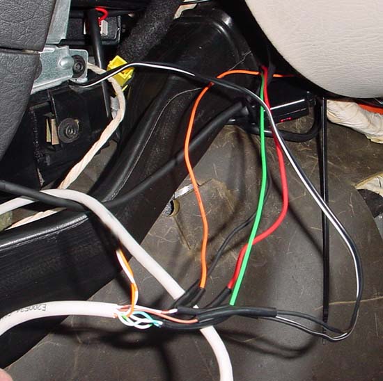
The two orange wires are not used. Remember to slip a piece of heat shrink tubing on the wiring before you make your connections. After making the connections, solder them together and shrink the tubing. The picture below shows the connection made up.
Connections from V60 electronics box to RJ-45 cable made up.
Make up all the soldered connections shown above.
Plug all connectors into the electronics box.
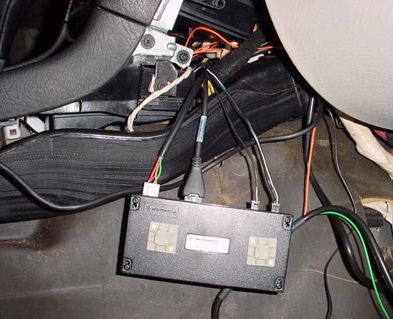
I mounted plastic tie wrap holders on top of the electronics box so it could be secured once it is put in under the radio.
Electronics box with tie wrap holders mounted and all connections plugged in. Route all the wires neatly, tie wrap them in place, and install the electronics box under the radio.
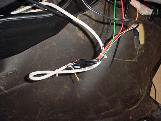
Wiring tied up. Note tie wraps on each side of soldered connections. This relieves stress on the soldered connection.
Make up the cell antenna connection to the Terk CFR-903 antenna. If you are using the stock antenna, you will need to route an antenna extension cable to the trunk. This could be a very difficult project in itself.
Testing
Now is the time to test the unit. Plug the RJ-45 connector in under the armrest. The reason why it was not plugged in before was to keep all of the electronics box wiring deenergized while making it up.
Don't plug in the RJ-45 connector until all connections are made and you are ready to test the phone. This will prevent the electronics box wiring deenergized while the connections are made up.
Turn you ignition on, put your V60 phone in the cradle, and listen to the hands free speaker make noise. If the radio is on, it should mute the radio. Try making a phone call, did it work in hands free mode? Test the microphone too, it's best to talk to somebody.
If it works, you can put it all together. If it doesn't, you need to start troubleshooting. This procedure does not include a troubleshooting guide.
Microphone Installation
The microphone that is supplied with the V60 hands free kit is used versus the built in stock microphone. Problems could occur using the stock microphone due to impedance matching to the new hands free kit. It is easier and simplier to install the kit microphone.
The supplied microphone wire was just long enough. It is mounted on the driver's side of the sunroof control panel.
First, remove the sunroof control panel by carefully prying off the dome light cover using a flat blade screwdriver. Remove the two phillips head screws and the panel will drop down.
Remove the dome light cover and remove two
screws to remove sunroof control panel.
After the sunroof control panel is removed, push the microphone from the front side of the headliner through to the sunroof controller hole. Just pull down on the headliner, it clears quite easily.
The microphone will easily fit through headliner without removing it.
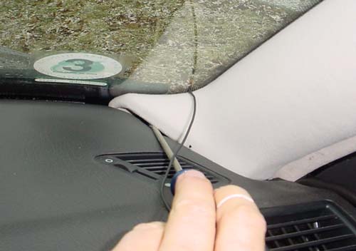
Then route the wire along the headliner at the top of the windshield, and down along the "A" pillar. Use a screwdriver to lift the trim up while pushing the wire in, it will then slip behind and under it, giving adequate length to reach the console.
Use a long screwdriver to lift up the trim to tuck the wire down and around it. This is necessary to get enough length to make it to the electronics box.
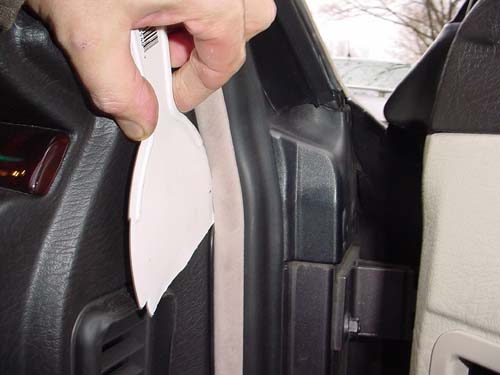
Push it in along the door frame. Pop the plastic trim out at the door jam using a flat head screwdriver and route the wire past the fuse box. Get a plastic paint spatula from Home Depot shown in the picture below to do all the wire routing. They can be found in the paint department for about $1.00.
Push the wire in along the trim work using a plastic paint spatula.
Route the wire under the glove box and tie up with tie wraps or tape. If using the Terk external antenna, route this wiring at the same time. You will have to be slightly creative to get it to fit, it is just long enough to make it from the sunroof control panel to the electronics box under the radio.
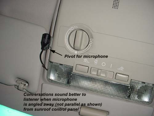
Once the wire is routed, reinstall the sunroof control panel. I used the velcro mounted supplied with the kit to attach the microphone to the sunroof control panel. This installation allows for the microphone to be angled away from the position shown in the picture, which makes for better sounding conversations on the other end.
Microphone installation using supplied velcro. The microphone pivot mount was used. The V60 kit comes with three different style microphone mounts.
Antenna Installation
If using the Terk CFR-903 antenna, it is mounted on the inside of the top of the front window in front of the passenger seat. The kit states that the antenna works with all Motorola and Nokia hands free kit, but I found that the connectors were not plug and play. This required a trip to Radio Shack and a little imagination to make a jumper cable to connect the cradle to the antenna.
Terk CFR-903 antenna. Once it is tucked under the headliner, it is not visible from the inside or outside.
The cable is routed in the same fashion as the microphone cable above. Put this cable in second because the microphone cable length is relatively short and must be routed precisely.
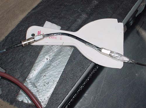
To make the jumper cable to connect the two antenna cables, two connectors were bought from Radio Shack that fit the V60 cradle. The Terk cable is a smaller size. The Radio Shack connectors must accept the male portion of the coaxial wire, the coaxial part on the V60 cradle and Terk external antenna are both female.
Buy a DB-58 coaxial wire or short piece with connectors on it and cut them off, and strip both ends, making a 5" piece. To ground out the Terk side which is smaller, use some tin foil on the outside of the connector to build it up so it would touch the Radio Shack connector. Then wrap it with some type of tape. The V60 cradle side is a direct fit up.
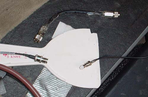
Jumper cable made up using Radio Shack connectors and coaxial wire. Note Terk antenna wire on right is smaller than the other three coaxial connectors on jumper cable and V60 cradle wire.
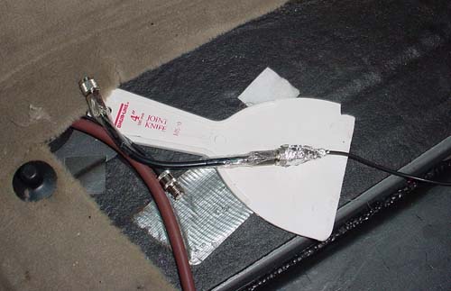
Terk antenna made up to jumper cable. To get the shield wire connected between the Terk antenna and the jumper cable, tin foil was used to build up the outside of the Terk connector. Ensure it contacts the Terk antenna metal and the Radio Shack connector metal. Then tape it up.
All cables made up. From left to right, V60 cradle external antenna wire, jumper wire, Terk antenna wire.
Putting the Side Panel Back On
Putting the side panel on is a little tricky. It needs to be installed in the same fashion as it was removed.
With all the wiring in place and tucked away, slide the panel back in, routing the phone wires to the location shown below.
When installing the side panel, route the phone wires as shown here.
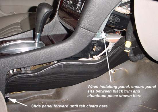
Slide the panel back in, top of the panel goes in first, with the bottom of the panel angled back towards the passenger's door. Slide the panel between the black trim and the aluminum plate shown in the picture below. The panel has a tendency to go behind the stainless steel plate. Most likely the aft end of the panel will need to be pulled over the passenger seat inboard rail.
Once the top is in, the back side of the panel must be slid forward until the rear tab clears the black trim piece. Once this is in (and you will most likely struggle with it), install the three screws that hold it in.